14
L
It is therefore necessary that all input and output signals
required for the control of the controller are, electrically, safely
separated by measures outside the controller and have
another protection against direct contact (double basic
insulation).
For operation with tacho voltage feedback the control
electronics has a simple basic insulation. Take measures
outside the controller to ensure that input and output signals
of the control have a double basic insulation.
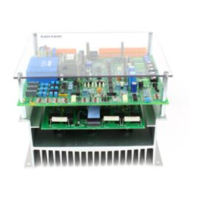
The protective cover above the controller board reduces the hazard
of accidental touching of live components. For the assembly and
during commissioning the cover must be removed.
Caution!
Removal of the protective cover and all settings must only be
carried out by qualified skilled personnel.
With removed cover, there is increased danger of accidental
contact with bare, live components on the controller board.
The protective cover must only be attached and removed when no
voltage is applied. The cover must be replaced after setting.
The temperature of the power semiconductors in the 483...485
units is monitored by a thermal sensor. If the heatsink temperature
exceeds the limit ϑ
limit
= 90 °C the controller sets controller inhibit
"RSP" and the firing pulses are set to the inverter limit position.
An electrical latching also prevents an automatic reconnection after
the controller has cooled. The latching can only be eliminated by
disconnection and reconnection of the mains!
Notes for the connection of controller and motor
Lenze controller Motor (acc. to DIN 42017 / VDE 0530 part 8)
Function Termina
l
Termina
l
other
designations
Motor type
Armature voltage +
-
Excitation voltage +
-
A
B
I
K
1B1
2B2
F1
F2
A1
B2, A2
E1
E2
DC motor uncompensated with commutating pole
winding
Armature voltage +
-
Excitation voltage +
-
A
B
I
K
1C1
2C2
F1
F2
A1
C2
E1
E2
DC motor compensated with commutating pole
winding
Armature voltage +
-
A
B
A1
A2
Permanent magnet motor
DC tacho +
-
3
4
2A1
2A2
AC tacho +
with rectification -
3
4
3A1
3A2

 Loading...