Commissioning
8250BA0903 5-1
5 Commissioning
Stop!
If the connections +U
G
and -U
G
are reserved, the brake units and
all connected components can be destroyed.
It is therefore absolutely necessary to check the correct
connection of the terminals before switching on the unit.
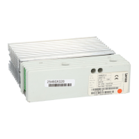
The two LEDs at the brake unit indicate the operating state:
• green LED:
illuminated, when the brake unit is supplied with voltage
and is ready for operation
• yellow LED:
illuminated, when brake unit is in braking operation
Note!
The deceleration time of the drive will be prolonged if the
feedback power is higher than the peak brake power of the
assigned brake resistor. In this case, the controller sets pulse
inhibit and indicates „ overvoltage“ .
Prolong the T
if
-time via the deceleration ramp at the
ramp-function generator or the QSP ramp at the controller or use
a lower-value brake resistor, if permitted.