l
6
EDBMB935X EN 8.0
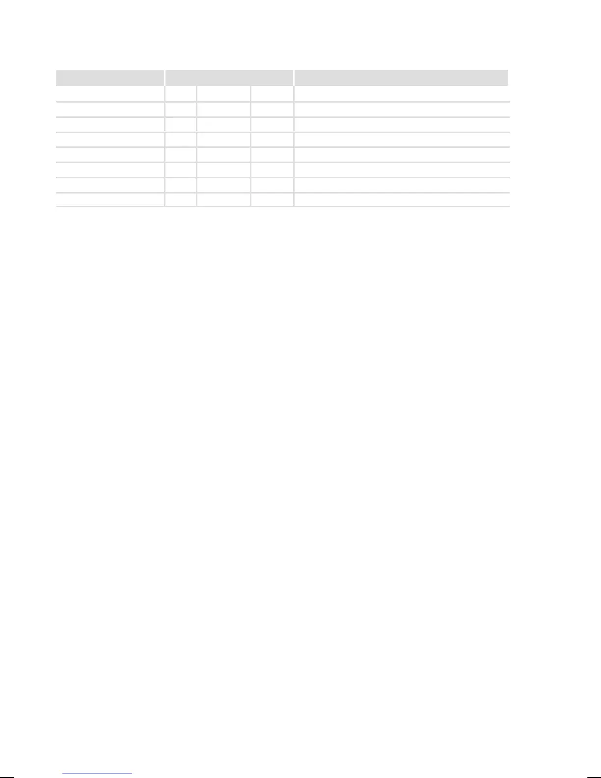
Document history
Material number Version Description
.;p] 8.0 08/2008 TD34 Extension by chapter 5.5
.7tG 7.0 11/2007 TD34 Complete revision
!R;ó 6.0 06/2004 – Revision of chapter 4
!NLc 5.0 06/2002 – Change of name
!NùW 4.0 02/2002 – Revision of the chapters 3.3.3 and 4.1.3
!HEx 3.0 04/2000 – Revision of chapter 4.3.2
!HEx 2.0 01/1997 – Revision of chapter 4
!H0m 1.0 08/1996 – First edition, monolingual
0Fig. 0Tab. 0
I Tip!
Current documentation and software updates concerning Lenze products can
be found on the Internet in the "Services & Downloads" area under
http://www.Lenze.com
© 2008 Lenze Drive Systems GmbH, Hans−Lenze−Straße 1, D−31855 Aerzen
No part of this documentation may be reproduced or made accessible to third parties without written consent by
Lenze Drive Systems GmbH.
All information given in this documentation has been selected carefully and complies with the hardware and
software described. Nevertheless, discrepancies cannot be ruled out. We do not take any responsibility or liability
for any damage that may occur. Necessary corrections will be included in subsequent editions.