27 RG-SFMOD
Drive Control & Communication
7.4 Basic Drive Status
AC Tech register 24 is a 6 word entity containing the drive’s status information. To read the entire status
block use Modbus function code 3 with a length of 6 to read starting at Modbus register number 40025.
The low byte of the third word in this block of data contains the operational status. If this is the only data
you want you can use Modbus function code 3 with a length of 1 to read register 40027.
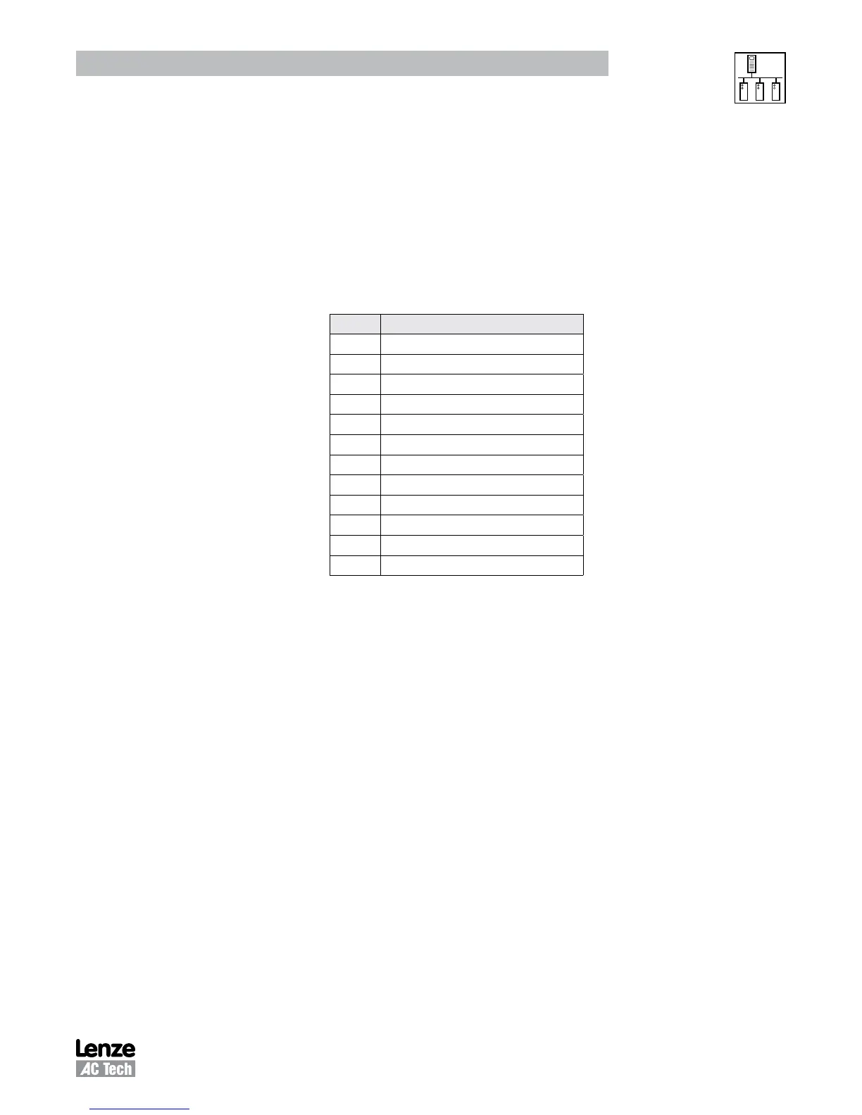
The value of that low byte of data corresponds to the following operational states:
Operational Status (byte D3L or Register #26 DL)
VALUE* OPERATIONAL STATE
0 FAULT LOCKOUT
1 FAULT
2 START PENDING
3 STOP
4 DC BRAKE
5 RUN AT 0Hz
6 RUN
7 ACCEL
8 DECEL
9 CURRENT LIMIT
10 DECEL OVERRIDE
11 LOWER TRANSISTORS SWITCHING ON
* This is the decimal equivalent value of the binary number of the bits in that byte.
7.5 Basic Drive Network Programming
The programming parameters of the SCF drive may be altered by a Modbus master. To do so simply write
the desired value to the appropriate Modbus register. The translation is as follows:
Modbus register number = SCF parameter number +51
As an example if you wanted to change the acceleration time (P19) of the SCF drive write the time desired
into Modbus register 40070.Note that time is written in 0.1 seconds (so 200 would be 20.0 sec).
 Loading...