EasyManua.ls Logo

Lenze ESV402N02TXB571 User Manual

Lenze ESV402N02TXB571
48 pages
To Next Page IconTo Next Page
To Previous Page IconTo Previous Page
Page #43 background imageLoading...
Page #43 background image
41
EDBSV571 EN 1.0
EN
Troubleshooting and Diagnostics
5.2 Drive Configuration Messages
When the Mode button is pressed and held, the drive’s display will provide a 4-digit code that indicates how
the drive is configured. If the drive is in a Stop state when this is done, the display will also indicate which
control source commanded the drive to Stop (the two displays will alternate every second).
Configuration Display
Format = x.y.zz x = Control Source:
L = Local Keypad
t = Terminal Strip
r = Remote Keypad
n = Network
y = Mode:
S = Speed mode
P = PID mode
t = Torque mode
C = Sequencer mode
zz = Reference:
CP = Keypad p q
EU = 0-10 VDC (TB-5)
E1 = 4-20 mA (TB-25)
JG = Jog
nt = Network
OP = MOP
P1...P7 = Preset 1...7
01...16 = Sequencer Segment
Example:
L.S.CP = Local Keypad Start control, Speed mode, Keypad speed reference
t.p.EU = Terminal Strip Start control, PID mode, 0-10 VDC setpoint reference
t.C.12 = Terminal Strip Start control, Sequencer Operation (Speed mode), Segment #12
n.t.p2 = Network Start control, Vector Torque mode, Preset Torque #2 reference
n.S.03 = Network Start control, Speed mode, Speed reference from Sequencer segment #03
Stop Source Display
Format = x.StP L.stp = Stop command came from Local Keypad
t.stp = Stop command came from Terminal Strip
r.stp = Stop command came from Remote Keypad
n.stp = Stop command came from Network
Question and Answer IconNeed help?

Do you have a question about the Lenze ESV402N02TXB571 and is the answer not in the manual?

Lenze ESV402N02TXB571 Specifications

General IconGeneral
BrandLenze
ModelESV402N02TXB571
CategoryDC Drives
LanguageEnglish

Summary

Safety Information

Technical Data

Model Ratings

Provides detailed electrical ratings across various voltage and phase configurations.

Installation

Electrical Installation Procedures

Guidelines for connecting power, motor, and control wiring safely.

Fuse and Cable Cross-Section Guide

Recommendations for fuses, breakers, and wiring sizes for different drive models.

Control Terminal Connections

Details on control terminal connections and their functions.

Commissioning

Parameter Setting and EPM Use

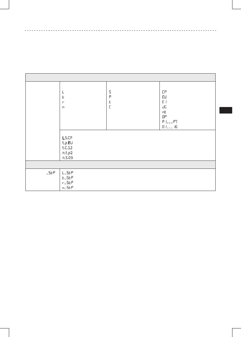
Illustrates parameter navigation and the use of the Electronic Programming Module.

Parameter Menu Overview

Introduction to the drive's parameter menu structure and basic setup.

Custom Modbus Register Map

Details specific Modbus registers for drive control, status, and diagnostics.

Troubleshooting and Diagnostics

Status and Warning Messages

Lists and explains status/warning messages, their causes, and recommended remedies.

Fault Messages and Remedies

Detailed list of fault codes, their causes, and recommended troubleshooting steps.

Related product manuals