Mechanical installation
Mounting of g500 short/servo adapters with clamping connection
Maximum permissible load at the motor adapter
4
28
Lenze ¯ MA 12.0012 ¯ 4.0
4.3.6 Mounting of g500 short/servo adapters with clamping connection
Important notes
¯ The transmission is made in a force−fitting manner via a clamping connection.
Greases, oils and other substances which reduce the friction factor reduce the
torque to be transmitted which is why these should be avoided in the connection.
¯ The motor shaft diameter must be designed with fit k6.
¯ The motor centering diameter must be designed with fit j6.
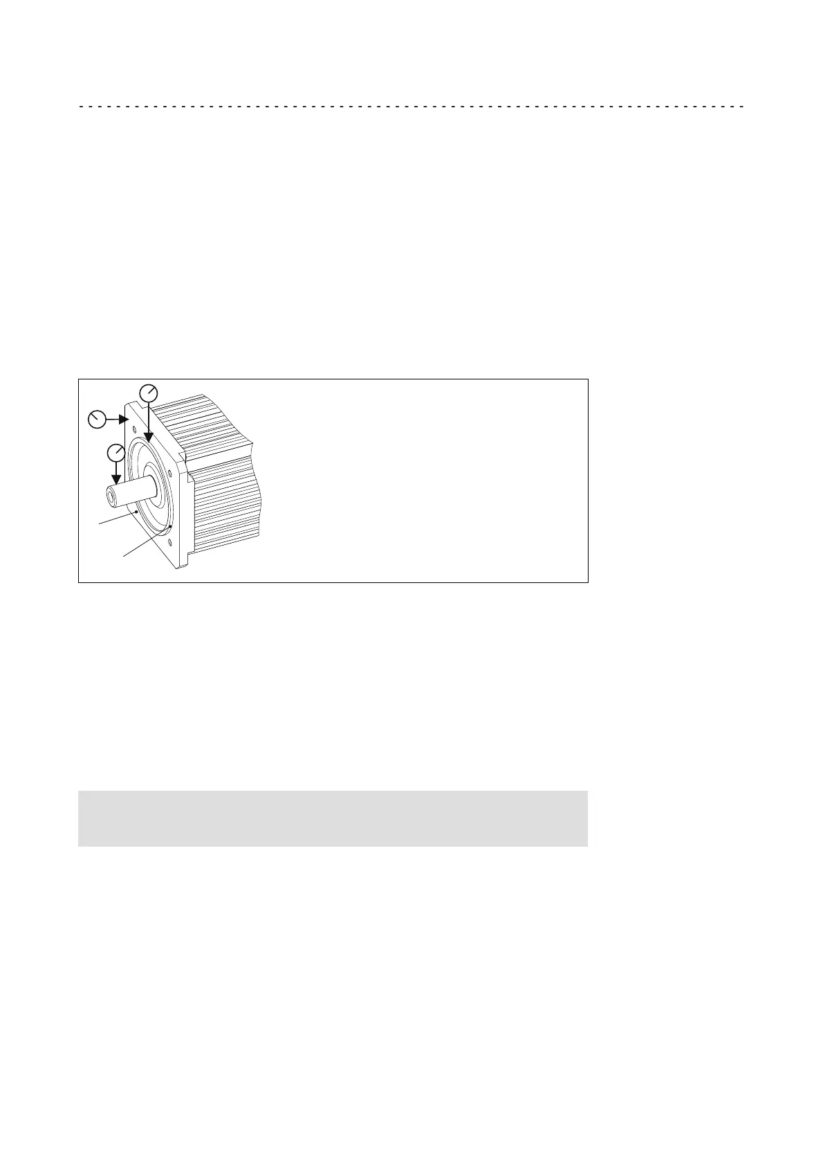
¯ With regard to smooth running tolerance of the motor shaft, concentricity of the
centering and axial runout of the mounting flange, the motor must fulfil the
requirements according to DIN 42955 R (reference values for smooth running <
0.025 mm; axial runout and concentricity < 0.05 mm).
4
5
Fig. 4 Measurement of the surfaces of smooth running, axial runout and concentricity
4 Motor flange
5 Centering
Preparation
¯ Ensure standstill of the drive system and prevent any machine movement.
¯ The drive system must have cooled down.
¯ The motor must be deenergised.
Note!
Lenze recommends the use of smooth motor shafts without slots!
7. Check:
¯ If the drill depth in the hollow drive shaft is sufficient for the motor shaft.
– For this purpose, compare the drill depth from the flange face with the distance
of motor shaft front side to the motor flange.
¯ Check of the motor shaft journal, the hollow shaft bore of the gearbox drive shaft,
the flange faces and the centering at the motor and gearbox for damages.
In the event of irregularities, parts have to be reworked or sorted out.
 Loading...