WARNINGS AND CAUTIONS:
• If you are not sure about any part of these instructions, consult an electrician.
• Clean outer surface gently with damp cloth only. DO NOT use soaps or cleaning liquids.
• No user serviceable components. DO NOT attempt to service or repair.
• Use this device WITH COPPER OR COPPER CLAD WIRE ONLY.
WARNINGS AND CAUTIONS:
• TO AVOID FIRE, SHOCK, OR DEATH; TURN OFF POWER AT CIRCUIT BREAKER OR FUSE AND TEST THAT THE
POWER IS OFF BEFORE WIRING!
• To be installed and/or used in accordance with electrical codes and regulations.
• To avoid overheating and possible damage to this device and other equipment, DO NOT install to control a receptacle.
• DO NOT control a load in excess of specied ratings or you may damage property, or cause injury or death.
Push down tabs per
diagram, one at a time and
rotate forward to release
1 2
0 3
1 2
0 3
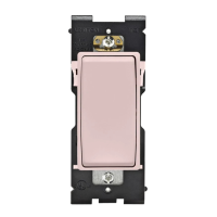
Attach new face by inserting
bottom hinge tabs, then pivot
and snap the color kit to attach
Tools needed to install your Device
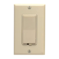
Changing the color of your device
Slotted/Phillips Screwdriver Electrical Tape Pliers
Pencil Cutters Ruler
√
INSTALLING YOUR DEVICE
NOTE: Use check boxes when Steps are completed.
ONOFF
ONOFF
ONOFF
ONOFF
ONOFF
ONOFF
ONOFFONOFF
ONOFF
ONOFF
ONOFF
ONOFF
Step 1
WARNING: TO AVOID FIRE, SHOCK, OR DEATH;
TURN OFF POWER at circuit breaker or fuse and test
that power is off before wiring!
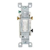
Single-Pole
1. Line (Hot)
2. Neutral
3. Ground
4. Load
Step 2
Identifying your wiring application
(most common):
NOTE: If the wiring in the wall box
does not resemble any of these
congurations, consult an electrician.
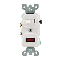
WIRING SENSOR:
Connect wires per WIRING DIAGRAM as follows:
NOTE: A ground connection is required to operate. Use the ground wire
in the electrical box for ground connection. If there is no ground wire,
make sure the electrical box is grounded and attach the ground wire to
the box with a screw.
• Green or bare copper wire in wall box to Green terminal screw.
• Line Hot wall box wire to terminal screw marked "BK".
• Load wall box wire to terminal screw marked "RD".
• Proceed to Step 5.
Hot (Black)
Neutral (White)
Red
Black
Black
LOAD
Line
120VAC, 60 Hz
Green
Ground
Terminal
Screw marked
Red (RD)
2
BK
RD
Terminal
Screw marked
Black (BK)
4
1
3
Single Pole Wiring Application:
Step 4
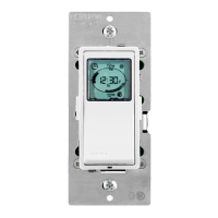
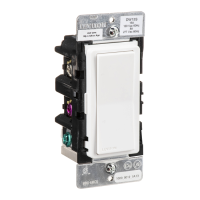
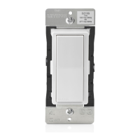
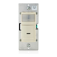
Single Pole Wide View Motion Activated Light Control
Cat. No. IPS02, IPV02 - INDOOR USE ONLY
Ratings: 120VAC, 60Hz - 300W Incandescent - 150W LED, CFL - 200VA ELV, MLV - Fluorescent 2.5A - Resistive - 1/6th HP
INSTALLATION INSTRUCTIONS
PK-93020-10-00-2B
FEATURES
• Cat. No. IPS02 and IPV02 have a sensing area of coverage of 30 ft. x
30 ft., and a sensing angle of 180
O
(see Sensing Area Coverage gure
on page 2)
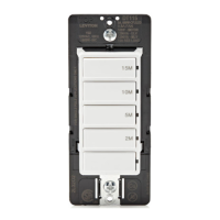
• Adjustable light and time-delay controls are located on the front of the
device. See adjustment setting section on page 2 for details.
• LED indicator is used to alert the user of the status of the device.
• Adjustable Time Delay setting for 30 seconds, 5 minutes,
15 minutes and 30 minutes.
• Occupancy sensors can be converted to vacancy sensors.
See Adjustment Section page 2.
LOCATION / MOUNTING
The device responds to temperature changes and care should be
taken when mounting the device. DO NOT mount directly above a heat
source, in a location where hot or cold drafts will blow directly on the
sensor, or where unintended motion (e.g., hallway trafc) will be within
sensor’s eld-of-view.
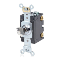
Preparing and connecting wires:
This device can be wired using side wire terminal screws.
Choose appropriate wire stripping specications accordingly.
Strip Gage
(measure bare wire
here or use gage on
back of the sensor)
5/8”
(1.6 cm)
Side Wire Connection
Side wire terminals accept #14-12
AWG solid copper wire only.
Step 3
Back Wire
Back wire openings use #14-12
AWG solid copper wire only.
BK
Your device may include color options. To change color of the face
proceed as follows:
• Make sure that the ends of the wires from the wall box are straight
(cut if necessary).
• Remove insulation from each wire in the wall box as shown.