3-Way or More Applications (Multi-Location)
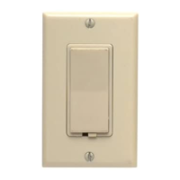
Decora
®
Manual-ON Occupancy Sensor Remote
California Title 24 2008 Compliant
Cat. No. IPV0R - 120VAC, 60Hz
For use with Cat. No. IPS15 and IPV15 Sensors
INSTALLATION INSTRUCTIONS
WARNINGS AND CAUTIONS:
• TO AVOID FIRE, SHOCK, OR DEATH; TURN OFF POWER AT CIRCUIT BREAKER OR FUSE AND TEST THAT THE POWER IS OFF BEFORE WIRING!
• To be installed and/or used in accordance with electrical codes and regulations.
• To avoid overheating and possible damage to this device and other equipment, DO NOT install to control a receptacle.
• Use only one IPS15 or IPV15 sensor in a multi-location circuit with up to 9 VP0SR-10 coordinating Vizia+™ switch remotes without LEDs or up to
4 IPV0R-1L sensor remotes or 4 VP0SR-1L Vizia+™ matching remotes with LEDs.
WARNINGS AND CAUTIONS:
• If you are not sure about any part of these instructions, consult an electrician.
• The Manual-On Occupancy Sensor Remote is intended to replace additional 3-Way and 4-Way switches when used with the IPS15 and
IPV15 Occupancy Sensors.
• Do not touch the surface of the lens. Clean outer surface gently with damp cloth only. DO NOT use soaps or cleaning liquids.
• Use this device WITH COPPER OR COPPER CLAD WIRE ONLY.
4-Way Wiring of Sensor Remote with IPS15/
IPV15 Sensor:
Step 4b
TOOLS NEEDED TO INSTALL YOUR DEVICE
INSTALLING YOUR REMOTE
NOTE: Use check boxes when Steps are completed.
√
Slotted/Phillips Screwdriver Electrical Tape Pliers
Pencil Cutters Ruler
ONOFF
ONOFF
ONOFF
ONOFF
ONOFF
ONOFF
ONOFFONOFF
ONOFF
ONOFF
ONOFF
ONOFF
Step 1
WARNING: TO AVOID FIRE, SHOCK, OR DEATH;
TURN OFF POWER at circuit breaker or fuse and test
that power is off before wiring!
Step 2
Identifying your wiring application
(most common) -
NOTE: If the wiring in the wall box
does not resemble any of these configurations, consult an
electrician.
4-Way
1. First Traveler – note color
2. Second Traveler – tagged
3. Neutral
4. Ground
5. Third Traveler – note color
6. Fourth Traveler – tagged
NOTE: For matching remote
w/LEDs installation, the First
Traveler becomes Line Hot.
3-Way
1. Line or Load (See important
instruction below)
2. Neutral
3. Ground
4. First Traveler – note color
5. Second Traveler – note color
NOTE: For matching remote
w/LEDs installation, the First
Traveler becomes Line Hot.
3-Way Wiring of Sensor Remote with
IPS15/IPV15 Sensor:
Step 4a
IMPORTANT:
For 3-Way applications, note that one of the screw terminals from
the old switch being removed will usually be a different color (Black) or
labeled Common. Tag that wire with electrical tape and identify as the
common (Line or Load) in both the sensor wall box and remote wall box.
For 4-Way applications, note that the old switch being removed will
have 4 screws plus a ground screw. Tag the two same color insulated
wires with electrical tape.
BK
3-Way
WH
BK
RD
3-Way
WH
Terminal
Screw marked
White (WH)
Terminal
Screw marked
White (WH)
Terminal
Screw marked
Red (RD)
3
1
3
2
4
IPS15, IPV15 SensorIPV0R Remote
Additional
Neutral Wire
Terminal
Screw
marked
3-Way
Terminal
Screw
marked
Ground
Terminal
Screw
(Green)
Terminal
Screw
marked
3-Way
Terminal
Screw
marked
Black (BK)
Ground
Terminal
Screw
(Green)
5
4
2
1
5
Hot (Black)
Neutral (White)
IPS15, IPV15 SensorIPV0R Remote
3-Way
RD
WH
BK
3-Way
WH
BK
Black
AC, 60Hz
Green
Ground
Green
Ground
LOAD
NOTE: The Occupancy Sensor must be installed in a wall box that has a Load
connection. The sensor remote must be installed in a wall box with a Line Hot
connection and a Neutral connection. A Neutral wire to the sensor remote needs
to be added as shown. If you are unsure about any part of these instructions,
consult an electrician. NOTE: Maximum wire length from sensor to all installed
remotes cannot exceed 300 ft (90 m).
WIRING SENSOR REMOTE OR VIZIA MATCHING SWITCH
REMOTE (3-Way wall box with Line Hot connection):
Connect wires per WIRING DIAGRAM as follows:
NOTE: Use backwire connection when connecting two wires to one screw terminal.
• Green or bare copper wire in wall box to Green terminal screw on Sensor
Remote or Vizia Matching Switch Remote.
• Line Hot (common) wall box wire identified (tagged) when removing old
switch and First Traveler wall box wire to Sensor Remote terminal screw or
Vizia Matching Switch Remote terminal screw marked "BK".
• Second Traveler wall box wire from other 3-Way wall box to Sensor Remote
terminal screw marked "3-Way" or Vizia Matching Switch Remote terminal
screw marked "YL/RD" (note wire colors). This traveler from the remotes
must go to the terminal screw marked "3-Way" on the sensor.
• Neutral wall box wire to remote terminal screw marked "WH".
WIRING SENSOR (3-Way wall box with Load connection):
Connect wires per WIRING DIAGRAM as follows:
NOTE: Use backwire connection when connecting two wires to one screw terminal.
• Green or bare copper wire in wall box to Green terminal screw on sensor.
• Load wall box wire identified (tagged) when removing old switch to terminal
screw marked "RD" on sensor.
• First Traveler Line Hot to terminal screw marked "BK" on sensor.
• Remove Red insulating label from terminal screw marked "3-Way" on sensor.
• Second Traveler wall box wire (note color as above) to terminal screw
marked "3-Way" on sensor. This traveler must go to the terminal screw on
the Sensor Remote marked "3-Way" or to the terminal screw on the Vizia
matching switch remote marked "YL/RD".
• Neutral wall box wire to terminal screw marked "WH" on sensor.
BK
RD
3-Way
WH
BK
3-Way
WH
(3-Way Wall box from Step 2)
(3-Way Wall Box from Step 2)
Terminal
Screw marked
White (WH)
Terminal
Screw marked
White (WH)
3
2
4
Terminal
Screw marked
White (WH)
3
1
Additional
Neutral Wire
Additional
Neutral Wire
BK
YL/RD
WH
3
6
2
1
Terminal
Screw
marked
Yellow/Red
(YL/RD)
Terminal
Screw
marked
Black (BK)
5
5
Terminal
Screw marked
Red (RD)
1
5
4
Terminal
Screw
marked
3-Way
Terminal
Screw
marked
Black (BK)
Ground
Terminal
Screw
(Green)
Terminal
Screw
marked
3-Way
Terminal
Screw
marked
Ground
Terminal
Screw
(Green)
Ground
Terminal
Screw
(Green)
4
2
Hot (Black)
Neutral (White)
IPS15, IPV15 SensorIPV0R Remote VP0SR-1L Remote
YL/RD
3-Way
RD
WH WH
BK
3-Way
WH
BK
BK
Line
Green
Ground
Green
Ground
LOAD
Green
Ground
NOTE: The Occupancy Sensor must be installed in a wall box that has a Load
connection. The sensor remote must be installed in a wall box with a Line Hot
connection and a Neutral connection. A Neutral wire to the sensor remote needs to
be added as shown. If you are unsure about any part of these instructions, consult
an electrician. NOTE: Maximum wire length from sensor to all installed remotes
cannot exceed 300 ft (90 m).
WIRING SENSOR REMOTE OR VIZIA MATCHING SWITCH REMOTE
(3-Way wall box with Line Hot connection):
Connect wires per WIRING DIAGRAM as follows:
NOTE: Use backwire connection when connecting two wires to one screw terminal.
• Green or bare copper wire in wall box to Green terminal screw on Sensor
Remote or Vizia Matching Switch Remote.
• Line Hot (common) wall box wire identified (tagged) when removing old switch
and First Traveler wall box wire to Sensor Remote terminal screw or Vizia
Matching Switch Remote terminal screw marked "BK".
• Second Traveler wall box wire from 4-way wall box to Sensor Remote terminal
screw marked "3-Way" or Vizia Matching Switch Remote terminal screw marked
"YL/RD" (note wire colors). This traveler from the remotes must go to the
terminal screw marked "3-Way" on the sensor.
• Neutral wall box wire to remote terminal screw marked "WH".
WIRING SENSOR REMOTE OR VIZIA MATCHING SWITCH REMOTE
(4-Way wall box):
Connect wires per WIRING DIAGRAM as follows:
NOTE: Use backwire connection when connecting two wires to one screw terminal.
• Green or bare copper wire in wall box to Green terminal screw on Sensor
Remote or Vizia Matching Switch Remote.
• First Traveler and Third Traveler wall box wires to Sensor Remote or Vizia
Matching Switch Remote terminal screw marked "BK".
• Second Traveler (tagged) and Fourth Traveler (tagged) wall box wires to Sensor
Remote terminal screw marked "3-Way" or Vizia Matching Switch Remote
terminal screw marked "YL/RD" (note wire colors). This traveler from the
remotes must go to the terminal screw marked "3-Way" on the sensor.
• Neutral wall box wire to remote terminal screw marked "WH".
WIRING SENSOR (3-Way wall box with Load connection):
Connect wires per WIRING DIAGRAM as follows:
NOTE: Use backwire connection when connecting two wires to one screw terminal.
• Green or bare copper wire in wall box to Green terminal screw on sensor.
• Load wall box wire identified (tagged) when removing old switch to terminal
screw marked "RD" on sensor.
• First Traveler Line Hot to terminal screw marked "BK" on sensor.
• Remove Red insulating label from terminal screw marked "3-Way" on sensor.
• Second Traveler wall box wire (note color as above) to terminal screw marked
"3-Way" on sensor. This traveler must go to the terminal screw on the Sensor
Remote marked "3-Way" or to the terminal screw on the Vizia matching switch
remote marked "YL/RD".
• Neutral wall box wire to terminal screw marked "WH" on sensor.
CHANGING THE COLOR OF YOUR DEVICE
Your device may include color options. To change color of the face
proceed as follows:
1 2
0 3
Push down
tabs per
diagram,
one at a time
and rotate
forward to
release
Attach new
face by
inserting
bottom hinge
tabs, then
pivot and
snap the
color kit to
attach
• Make sure that the ends of the wires from the wall box are
straight (cut if necessary).
• Remove insulation from each wire in the wall box as shown.
Strip Gage
(measure bare wire
here or use gage on
back of the remote)
5/8”
(1.6 cm)
Step 3
Preparing and connecting wires:
This remote can be wired using side wire terminal
screws or through backwire openings. Choose
appropriate wire stripping specifications accordingly.
Side Wire
Side wire terminals
accept #14-12 AWG
solid copper wire only.
Back Wire
Back wire openings
use #14-12 AWG solid
copper wire only.
BK