3. Slide the top cover away from the front panel,
removing it from the unit.
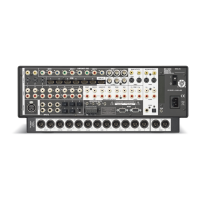
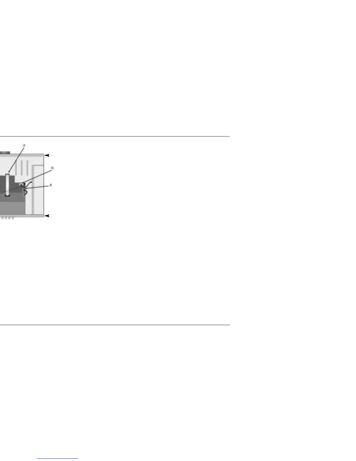
4. Disconnect the following cables, referring to the
illustration above:
A. The ribbon cable connecting the main board to
the video board. Disconnect the cable from
location J26 on the main board by gently
rocking the cable from side to side and pulling it
away from the board.
MC-12 to MC-12 Balanced Upgrade Instructions
MC-12
5
B. The ribbon cable connecting the opto/mic
board to the analog board. Disconnect the cable
from location J30 on the analog board. (The
opto/mic board is located between the main
board and the analog board, directly behind the
MICROPHONE INPUTS on the rear panel.)
C. The ribbon cable connecting the analog board
to the main board. Disconnect the cable from
location J29 on the main board by releasing the
locked tabs on the side of the connector, then
pulling the cable away from the board.
D. The power supply cable from location J26 on the
analog board. The power supply cable may
require more force to remove than the other
cables.
E. The power cable connecting the analog board
to the video board. Disconnect the cable from
location J25 on the analog board.
Main Board
Front Panel
Rear Panel
Analog
Board
Video Board
 Loading...