300598802_002_C0 - 10/2016 - © Leybold 7
Areas of application
1 Description
TRIVAC
®
T pumps are oil-sealed dual-stage rotary vane pumps. The number
in the type designation (4, 8, 16 or 30) indicates the pumping speed in m
3
·h
-1
.
TRIVAC
®
T pumps are capable of pumping gases and vapours and evacuat-
ing vessels or vacuum systems down into with the medium vacuum range.
The standard versions of the pump are not suited for pumping of oxygen ex-
ceeding the concentration as found in the atmosphere, and are also not suited
for pumping of hazardous gases or extremely aggressive or corrosive media.
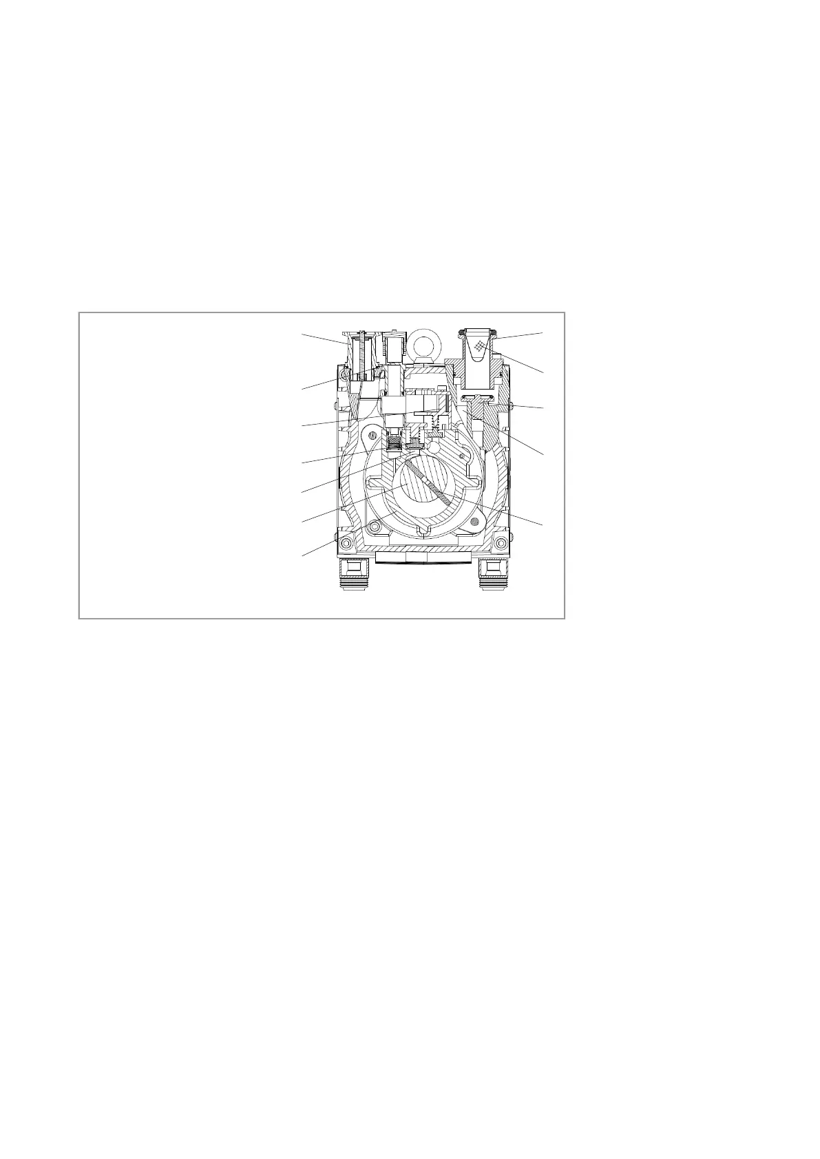
1.1 Function
The rotor (1/7), mounted eccentrically in the pump housing (1/6), has two radi-
ally sliding vanes (1/5) which divide the pump chamber into several compart-
ments. The volume of each compartment changes periodically with the rotation
of the rotor.
As a result, gas is sucked in at the intake port (1/1). The gas passes through
the dirt trap sieve (1/2), flows past the open anti-suckback valve (1/3) and then
enters the pump chamber. In the pump chamber, the gas is passed on and
compressed, after the inlet aperture is closed by the vane.
The oil injected into the pump chamber is used for sealing and lubricating. The
slap noise of the oil in the pump which usually occurs when attaining the ulti-
mate pressure is prevented by admitting a very small amount of air into the
pump chamber. Pump is already with silencing device.
The compressed gas in the pump chamber is ejected through the exhaust
valve (1/9). The oil entrained in the gas is coarsely trapped in the internal
splashguard(1/10); there the oil is also freed of mechanical impurities. The gas
leaves the TRIVAC
®
T through the exhaust port.
During compression, a controlled amount of air - the so-called gas ballast - can
be allowed to enter the pump chamber by opening the gas ballast valve. The
gas ballast stops condensation of vapours in the pump chamber up to the limit
of the water vapour tolerance as specified in the technical data for the pump.
Description
1 Intake port
2 Dirt trap
3 Anti-suckback valve
4 Intake channel
5 Vanes
6 Pump chamber
7 Rotor
8 Exhaust channel
9 Exhaust valve
10 Splashguard
11 Gas ballast
12 Exhaust port
Fig. 1 Sectional drawing of the TRIVAC
®
T
7
6
5
1
2
3
4
8
10
12
11
9

 Loading...