When checking components, turn the power off and discharge voltage.
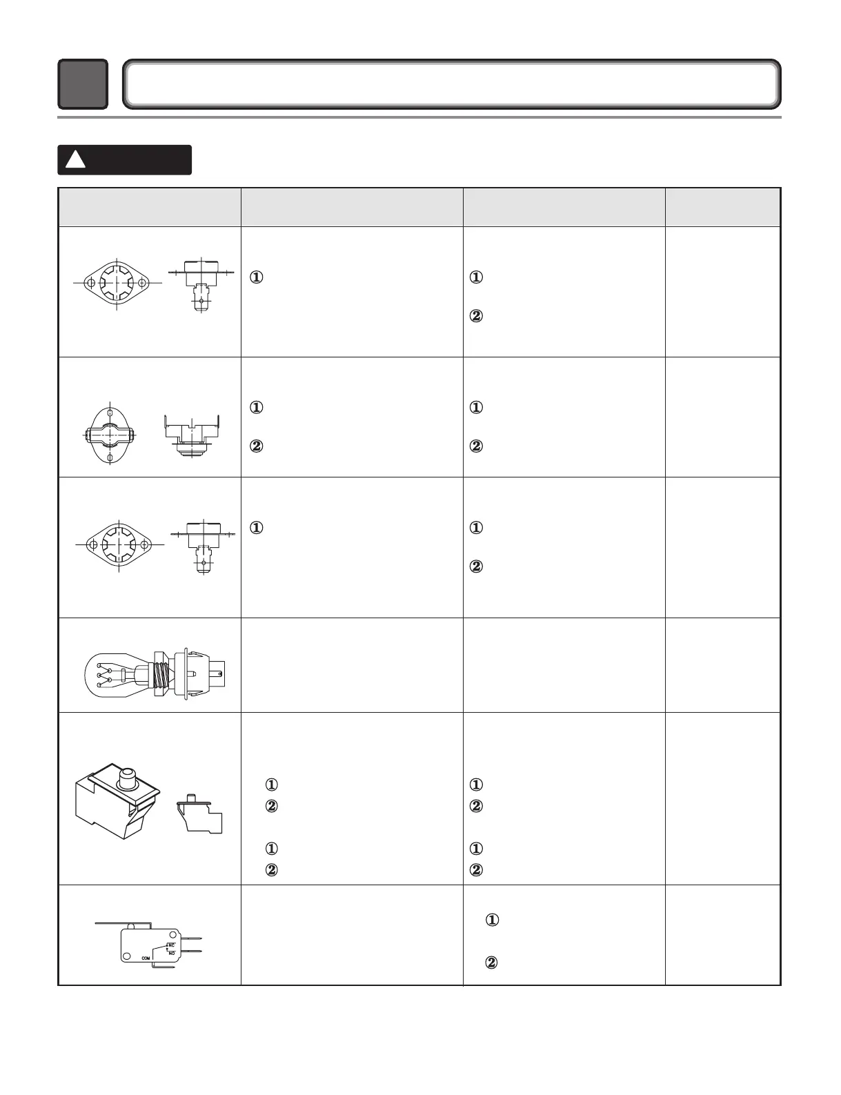
COMPONENT TESTING INFORMATION
5
!
CAUTION
Component Test Procedure Check result Remark
1. Thermal cut off
• Check Top Marking:
N140
Measure resistance of terminal
to terminal
Open at 284
±
`°F
(140
±
5°C)
G
Same shape as outlet thermostat.
If thermal fuse is open must
be replaced
Resistance value
Continuity (250°F
˨
) <1Ω
• Heater case-
Safety
• Electric type
2. Hi limit Thermostat
(Auto reset)
Measure resistance of terminal
to terminal
Open at 257
±
9°F
(125
±
5°C)
Close at 2W1
±XY
°F
(94
±
7°C)
Resistance value
∞
Resistance value <5Ω
• Heater case -
Hi limit
• Electric type
3. Outlet Thermostat
( Auto reset)
• Check Top Marking:
N85
Measure resistance of terminal
to terminal
Open at 185
±`
°F
(85
±
5°C)
G
G
Same shape as thermal cut off.
Resistance value
∞
Resistance value <5Ω
• Blow housing -
Safety
4. Lamp holder Measure resistance of terminal
to terminal
Resistance value:
80
Ω ~ 100Ω
6. Idler switch Measure resistance of the
following terminal:
COM - NC
1. Lever open
Resistance value <1Ω
2. Lever push (close)
Resistance value
∞
5. Door switch Measure resistance of the
following terminal
1) Door open
Terminal: COM - NC (1-3)
Terminal: COM - NO (1-2)
2) Door closed
Terminal: COM - NC (1-3)
Terminal: COM - NO (1-2)
Resistance value <1Ω
Resistance value
∞
Resistance value
∞
Resistance value <1Ω
∞