38
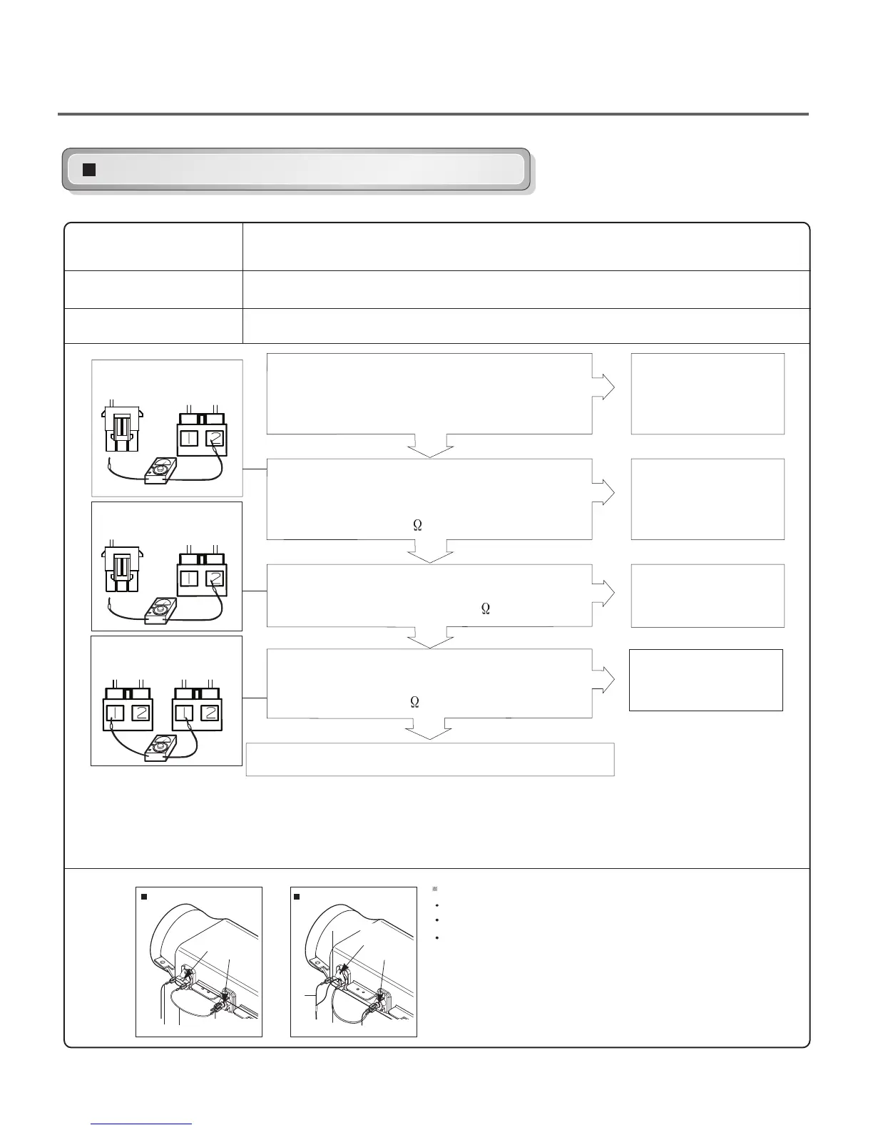
Test 6
Heater switch test - Electric Type
NO
NO
NO
NO
YES
YES
YES
YES
Caution
Trouble
Symptom
Measurement
Condition
Before measuring resistance, be sure to turn the power off, and do voltage discharge.
(When discharging, contact the metal plug of the power cord with a ground line.)
While operating, Heating will not work. Drying time takes longer.
After turning the power off, measure the resistance.
Enter diagnostic mode and press the
START/PAUSE button twice. Measure the
voltage between L2(Red wire on the terminal block)
and Black wire on the black tab relay connector.
Is the voltage 240 VAC?
Disconnect the BL2, black tab relay and white tab relay
connectors at the main PCB.
Measure the resistance between BL2-③(YL) and Black
wire on the black tab relay connector.
Is the resistance 18-22
?
Measure the resistance between BL2-③(YL) and
Blue wire on the white tab relay connector.
connector. Is the resistance 18-22
?
?
Measure the resistance between Black wire on the
black tab relay connector and Blue wire on the white
tab relay connector.
Is the resistance 36-44
Refer to the hi-limit thermostat and
thermal cut off component tests.
• Check power supply.
• Check wiring and
connectors to
the element.
• See element
component test.
• Check wiring and
connectors
to the element.
• See element
component test.
• Check wiring
and connectors to the
element.
• See element
component test.
TH3
L2(Red) L2S(White)
TH2
L2S(White)
L2
(Red)
TH3
TH2
L2D(White)
Only for FLOW SENSE modelOthers
Wires
L2(Red)
L2D(White) : Go to the duct(YL3 in main pcb)
L2S(White) : Go to the safety.
Tap Relay Connector
③
①
Black(Heater)
BL2
YL BK
YL
Tap Relay Connector
Tap Relay Connector
Black White
③
①
White(Heater)
BL2
BL BK
YL
YL BK BL BK
 Loading...