Installation
Location and Function of Controls
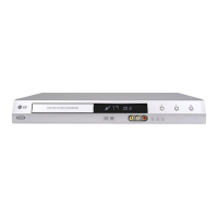
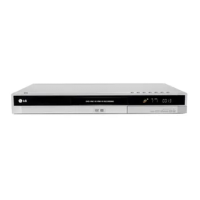
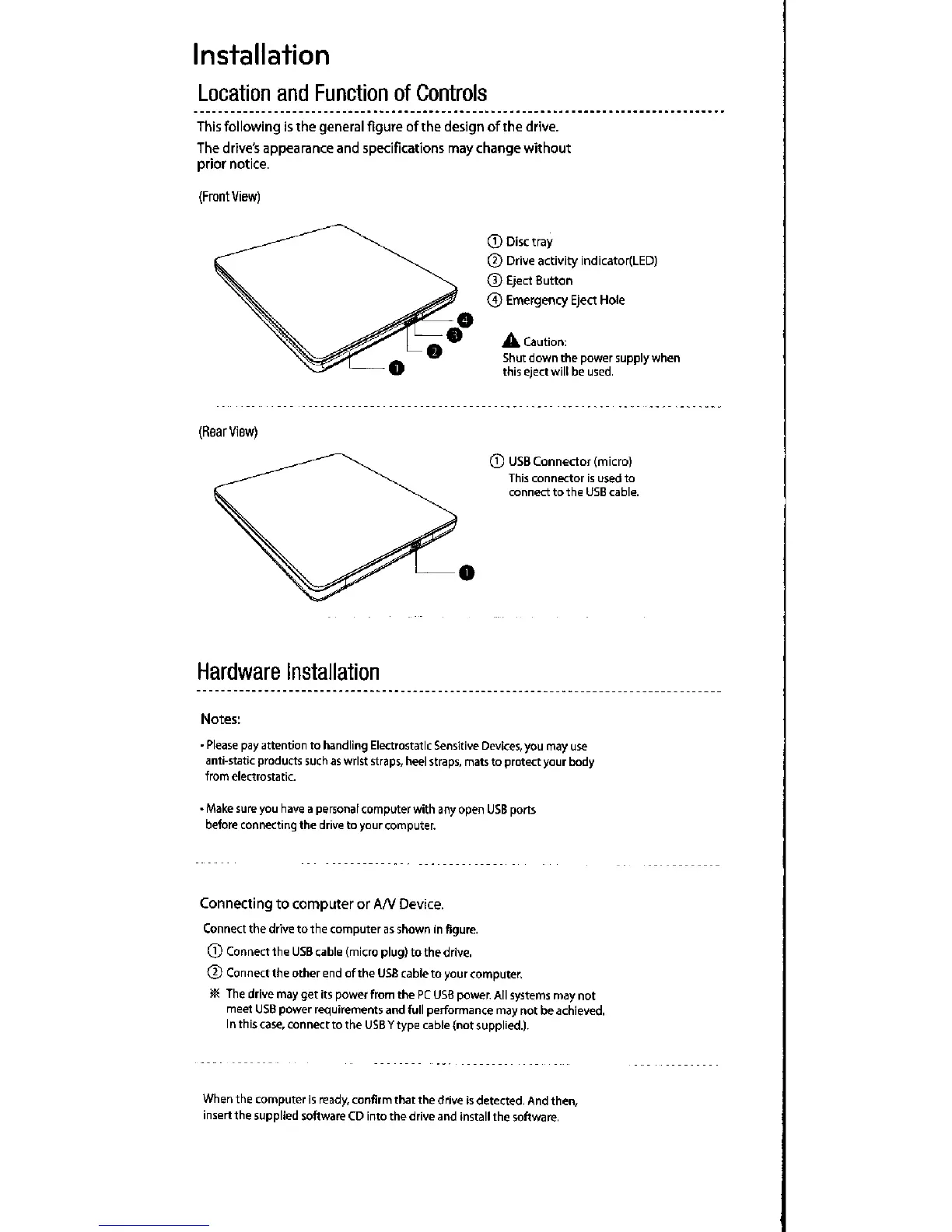
This following is the general figure of the design of the drive.
The drive's appearance and Specifications may change without
prior notice.
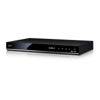
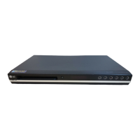
(Frontvlew)
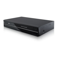
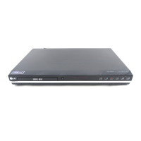
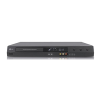
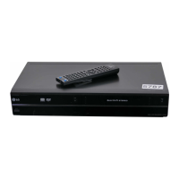
(F`earview)
Hardware Installation
® Disc tray
® Drive activity indicator(LED)
® Eject Button
® Emergency Eject Hole
A caution:
Shut down the power supply when
thls e/ect will be used.
® USB Connector (micro)
This connector is used to
connect to the USE cable.
Notes;
• Please pay attention to handling Electrostatlc Sensitive Devices, you may iise
anti-static products such as wrlst straps, heel straps, mats to protect your body
from electrostatic.
• Make sure you have a per5onal computer with any open USB ports
before connecting the drlve to your computer.
Connecting to computer ctr Arv Device.
Connect the drive to the computer as shown ln figure.
® Comect the USB cable (micro plug) to the drive.
®ConnecttheotherendoftheusBcabletoyourcomputer.
ae€ The drlve may get its powei from the PC Usa power. All systems may not
meet USB power requiretT`ent5 and full performance may not be achieved.
I n th is case, con nect to the USB y type cable (not supplied.).
When the computei is ready, confirm that the drive is detected, And then,
insert the supplied software CD Into the drive and install the software.
 Loading...