4
1
2
6
6 - 7
6 - 8
6 - 9
6 - 10
6 - 11
12 - 13
14 - 16
15 - 16
16
+
17
-
CONN-1
24Vac:
33 - 34
- / +
35 - 36
- / +
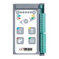
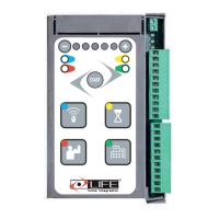
1 LINKS AND CONNECTIONS
1.1 Central Connections
Clamps
Description ( check electical scheme , page 5)
1
ANTENNA:
2
Antenna cable imput.
6
COMMON COMMANDS:
6 - 7
STOP: Imput N.C. Commands the gate’s halt.
To this can be connected to safety devices such as an emergency arrest button.
When released the command does not do an automatic arrest , it is instead necessary to give a new
movement command. Leave the bridge in place if no devices are installed.
6 - 8
OPEN:
Imput N.O. Commands the opening of the gate.
6 - 9
CLOSE : Imput N.O. Commands the gate’s halt.
6 - 10
SETP-BY-STEP:
Imput N.O. Command the gate’s actions following this commands :
SEMI-AUTOMATIC MODE : Open ,Stop,Close,Stop
FOUR STEPS MODE : Open,Pause,Close,Pause.
CONDOMINIUM MODE :
Open (automatic closing with the active pause time).
6 - 11
PHOTO:
Imput N.C for photocells and safety devices . While the gate is opening doesn’t intervene ,
12 - 13
RELE’ CONTACT :
14 - 16
ELECTIC LOCK:
Exit 12Vdc for the connection with the electric lock at 12Vdc 15VA; in order to activate
15 - 16
Exit 24 Vdc 25W max to connect the blinker
16
+
17
-
N.C. = contact normally closed - N.O = contact normally open
The command determines the opening of only one side. Can be given by remote or clamps
When using the terminal block a bridge will be obtained and the clamp n°8 will be OPEN , the clamp n°9 will CLOSE
this bridge will be connected to a switch at clamp n°6 common. The command PEDESTRIAN from terminl block
won’t have the OPEN and CLOSE commands.
EXIT 30 Vdc : To power various devices, max 200mA.
CONN-1
24Vac:
Input transformer power
33 - 34
Engine 2, if closed opens second.
Engine 1, if closed opens first.
PHOTO1: With option 1 Led 4 , the imput becomes N.C. in order to connect the photocell that
acts while in the Closing and Opening phase.
Clean contact Relè Max 3A , default for the connection to an open gate LED
With the activation OPTION 2 Led 2 becomes a command for the courtesy light timed at 3 minutes.
- / +
35 - 36
- / +
- Before proceeding with the links and connections carefully read what is presented in the PRESCRIPTIONS AND
WARNINGS FOR SECURITY and PRESCRIPTIONS AND WARNINGS FOR THE INSTALLATION.
- All of the linking and connecting operations must be performed with the power source disconnected , if the device is not
visible a sign must be applied : “ WARNING UNDER MAINTENANCE ”.
Stocking antenna input , use RG58-50 Ohm cable.
ANTENNA:
For the imputs: STOP - OPEN - CLOSE - STEP BY STEP - PHOTO.
BLINKER:
PEDESTRIAN:
Connections bottom of the control unit
CONN-2
Connection battery charger AGECH-2
while closing it dertermines the inversion of the motion until the complete opening.
Leave the bridge open if no devices are installed.
select the function from the Options meù n°1 Led n°3
Safety devices such as an emergency stop button can be connected to it.
When the command is released, automatic closing is never carried out but a new movement command
must be given. Leave the jumper if no device is provided.
input
Input
Input
Input
PHOTO1: With OPTION 1 Led 4, the input becomes N.C. for the connection of a photocell that intervenes
in Opening and Closing.
Input N.O. Controls the movement of the gate according to the following cycles:
FOUR STEPS MODE: Open, Pause, Close, Pause.
SEMI-AUTOMATIC MODE: Open, Stop, Close, Stop.
CONDOMINIUM MODE: Opens (automatic closure with active pause time).
PHOTO: N.C. input for photocells or safety devices. During the opening of the gate it does not intervene; in
closing it causes the inversion of the movement until the complete opening.
Leave the jumper if no device is provided.
PHOTO
RELAY CONTACT: Dry contact Relay Max 3A, default for the connection of an Open gate light. With the
activation of OPTION 2 Led 2 becomes a command for the courtesy light timed at 3 minutes.
RELAY CONTACT
ELECTRIC LOCK: 12Vdc output for connection of 12Vdc 15VA electric lock; to activate it, select the function
from the Options menu 1 Led 3.
ELECTRIC LOCK
FLASHING: 24 Vdc 25 W max output, for connection of the flashing lamp.FLASHING
PEDESTRIAN: The command causes an opening of only one leaf. It can be given by a remote control or by terminal board.
This terminal is obtained by bridging terminal 8 OPEN with terminal 9 CLOSE, this jumper then connects with a switch to
terminal 6 COMMON. The PEDESTRIAN command from the terminal board excludes the OPEN and CLOSE commands.
PEDESTRIAN
input
inputs
electrical
 Loading...