-
-
START
16
17
16
16
14
15
F3 3.15A-T
F2 10A-T
12 Vdc 15 VA
Relè 3A
30 Vdc 200mA Max
N.O.
COM.
24 Vac
13
12
POWER
13
12
POWER
AGECH2
F1 3.15A-T
CONN1
CONN2
230Vac
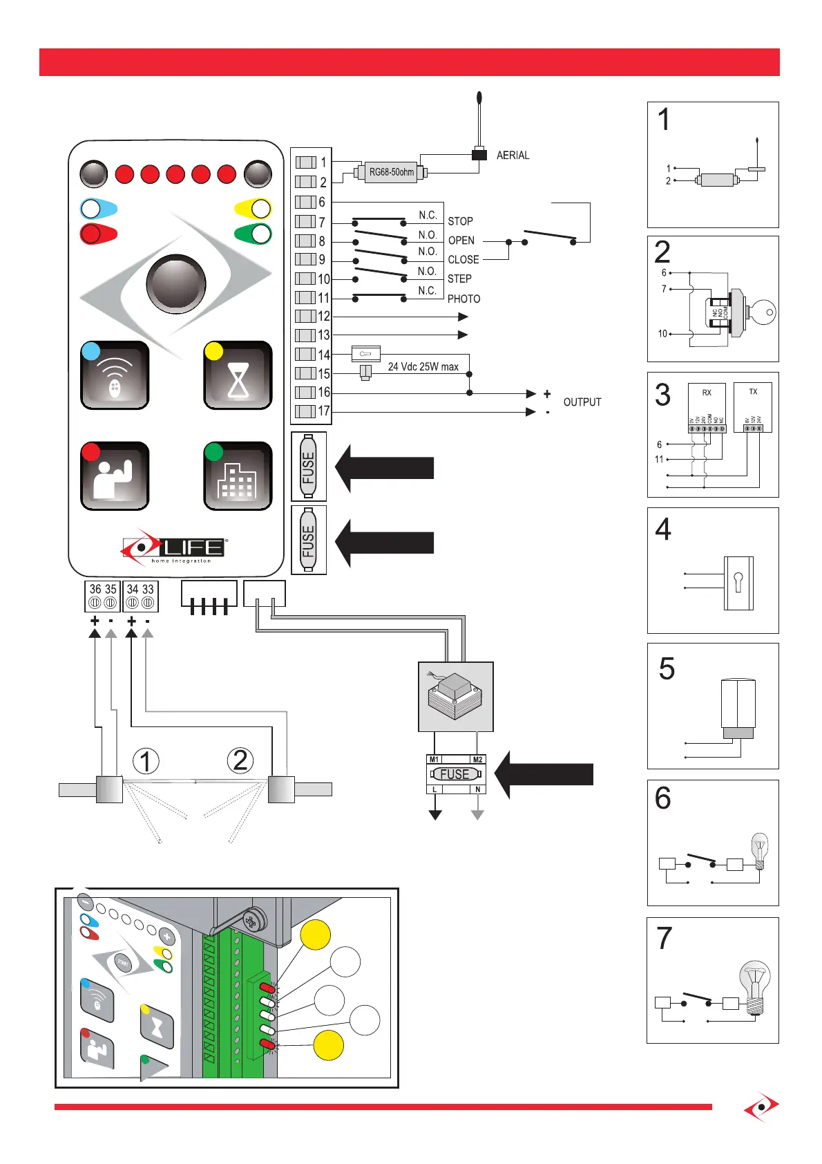
ELECTRICAL CONNECTION
ELECTRIC LOCK
FLASHING
INDICATOR LIGHT
DEFAULT
POWER
POWER
COURTESY LIGHT
OPTIONS N.2
Led 2 On
INDICATOR LIGHT N.6
COURTESY LIGHT N.7
FLASHING
ELECTRIC LOCK
L7
L8
L9
L10
L11
SIGNALS LED
The leds under the terminal block
show the entry state .
L7 and L11 are imputs N.C and must
be turned on , they turn o when
the corresponding imput is activated
L8-L9-L10 are imputs N.O. must be
turned o and they will automatically
turn on when the corresponding
imput is activated
COMMON COMMANDS
Relay
PEDESTRIAN
SIGNALING LED
The LEDs under the terminal block
indicate the state of the entrance.
L7 and L11 are N.C. inputs and they
must be turned on, they turn off when
the corresponding entrance is activated.
L8 - L9 - L10 are N.O. inputs
they must be off, they turn on
when the corresponding entrance
is activated.
 Loading...