LYTEMODE NETWORK POWERED HUB USER’S GUIDE INSTALLATION
7
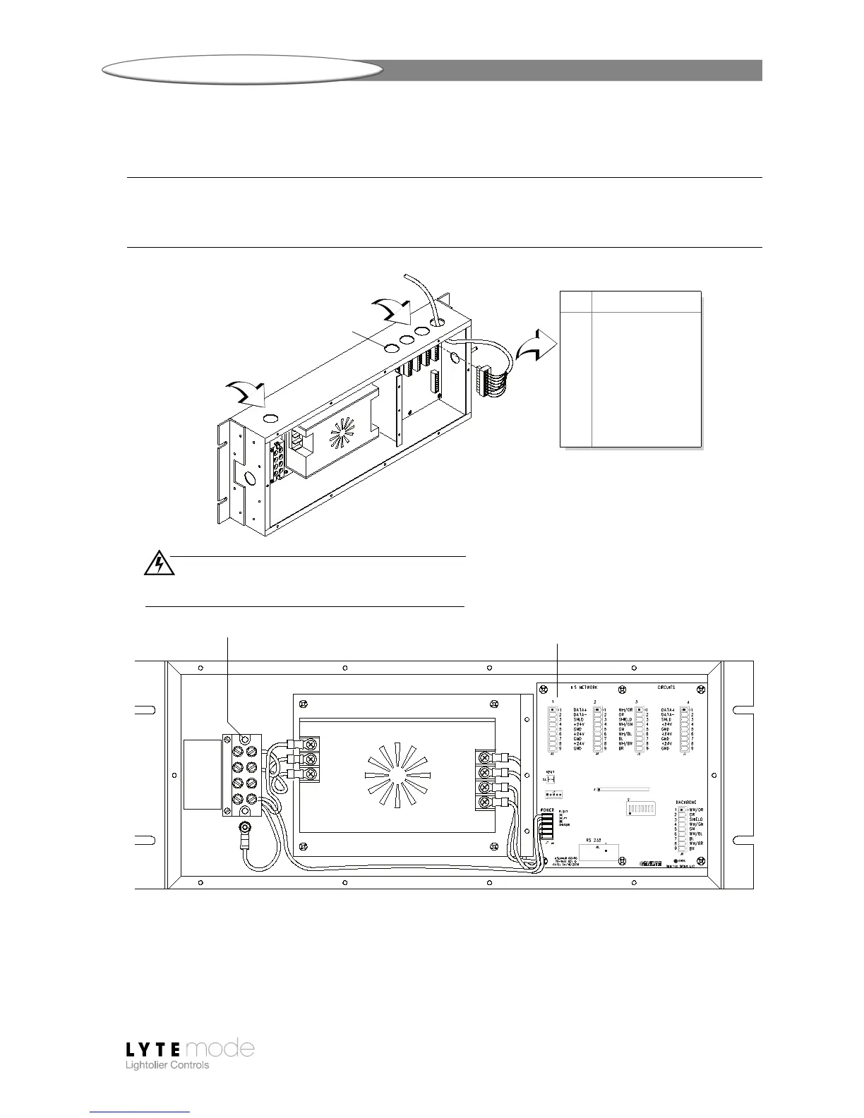
Step 6. As required, remove knock-out hole covers and route power input wires and
Lytemode ILS Network cables as shown in Figure
3.
Note: The Lytemode ILS Network consists of a single CAT5e cable connecting all Lytemode ILS
devices in a daisy-chain configuration. All units connect to the network using a 9-pin connector
(included).
Figure 3: Power and Lytemode ILS Network Connections
Step 7. Re-install compartment covers (Figure 2).
Step 8. Re-apply house power service.
NEUTRAL
LINE IN
GROUND
N/A
1 GND
2 AC LINE
3 AC NEUTRAL
Output + 4
Output +5
Output - 6
Output - 7
INTERIOR DETAIL
1 WH/OR (+ Data)
2 OR (- Data)
3SHIELD
4WH/GN (+ Volts)
5 GN (Ground)
6WH/BL (+ Volts)
7 BL (Ground)
8WH/BR (+ Volts)
9 BR (Ground)
9-Pin Lytemode Network Connectors
PIN SIGNAL
Knock-out Hole
WARNING!
Remove power from house service before connecting
any wiring or cables to the Network Powered Hub.
Route Power Wires
Route Network Cables
Lytemode Network
Input Power Connections
Connections (4)
 Loading...