Quick Start Guide
DVI-HDCP-TPS-TX210, DVI-HDCP-TPS-TX220
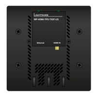
HDMI-TPS-TX210, HDMI-TPS-TX220
DP-TPS-TX210, DP-TPS-TX220
Further information
The document is valid with the following rmware version: 1.1.4
The User’s manual of this appliance is available at www.lightware.com.
See the Downloads section on the dedicated product page.
Contact us
sales@lightware.com
+36 1 255 3800
support@lightware.com
+36 1 255 3810
Lightware Visual Engineering LLC.
Peterdy 15, Budapest H-1071, Hungary
Doc. ver.: 2.1
19200111
Important Safety Instructions
Please read the supplied safety instruction document before using the product and keep it
available for future reference.
Introduction
Thank you for choosing Lightware TPS-TX200 series transmitter. The products have
HDBaseT
TM
integration with additional Lightware developments. The devices transmit HDMI/
DVI digital video signal up to 4K resolution, audio and control up to 170 m distance over a
single CAT cable (in case of DP-TPS transmitters the DP signal is converted to HDMI).
Compatible Devices
The transmitters are compatible with all Lightware
TPS receivers, matrix boards and third party
devices based on HDBase-T
TM
technology.
Power Supply Options
The transmitters can be powered:
Locally with the supplied 12V DC adaptor or Lightware’s rack mountable PSU, or
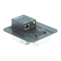
Remotely by a PoE-compatible power injector, like Lightware’s TPS-PI-1P1.
For more information please turn the paper.
TPS-TX/RX95 are not PoE-compatible, thus not able to remote power the TPS-TX200
series and vica versa. TPS-TX200 series contains PoE-compatible remote power function,
RX95 can be remote powered only by TX95 transmitter.
HDBaseT
TM
and the HDBaseT Alliance logo are trademarks of the HDBaseT Alliance.
Box Contents Connecting Steps
* Only for DVI-HDCP-TPS-TX220, HDMI-TPS-TX220 and DP-TPS-TX220 models.
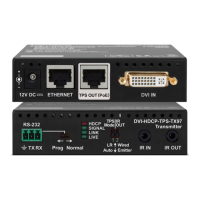
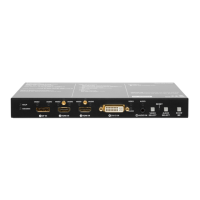
Front Views
Rear Views
Front Panel LEDs
Video Source
OFF: video source is not selected.
BLINKING: video source is selected but not active.
ON: video source is selected and active.
Audio Sources
OFF: audio source is not selected.
BLINKING: audio source is selected but not active.
ON: (with short pause): audio source is selected and the port is active but not embedded
to the output video stream (DVI output mode).
ON: (continuously): audio source is selected, the port is active and the audio is embedded
to the output video stream (HDMI output mode).
When Autoselect is enabled and audio signal is not present at all, audio LEDs blink.
HDCP LED
OFF: video output signal is not encrypted with HDCP.
ON: video output signal is encrypted with HDCP.
Autoselect LED
OFF: autoselect is disabled.
BLINKING: autoselect is enabled; searching for signal (audio LEDs also blink).
ON: autoselect is enabled; active signal is found (the LED of selected audio also lights).
Rear Panel LEDs
LIVE
OFF: device is not powered.
BLINKING (slow): device is powered and operational.
BLINKING (fast): device is in bootload mode.
ON: device is powered but no operation.
RS-232 LED
OFF: RS-232 ports (local and link) are in Pass-through mode.
BLINKING: command injection mode is active.
ON: RS-232 ports (local and link) are in Control mode.
SRVC
Reserved for future developments.
LINK
OFF: no TPS link between transmitter and receiver.
BLINKING (slow): low power mode is active.
BLINKING (fast): Ethernet fallback mode is active.
ON: TPS link is established, HDBaseT or Long Reach mode is active.
1
Autoselect LED LED gives feedback about the current Autoselect status.
2
HDCP LED LED gives feedback about the HDCP status of the output
signal.
3
DisplayPort input DisplayPort connector for DisplayPort audio/video signal.
4
HDMI input HDMI connector for DVI video or HDMI video and audio.
5
DVI-D input DVI-I connector for DVI-D video and audio.
6
Audio input 3.5 mm Jack connector for unbalanced analog audio
input signal.
7
Video select
button
Button for selecting a video source.
8
Audio select
button
Button for selecting an audio source.
9
Show me button Special functions can be reached using this button
(rmware upgrade (bootload) mode, DHCP settings,
restore factory default settings, condition launching in
Event Manager).
1
DVI-D output Local DVI-D output with the same A/V content as the
TPS output.
2
HDMI output Local HDMI output with the same A/V content as the TPS
output.
3
TPS output Locking RJ45 connector for HDBaseT
TM
signal
transmission.
4
Ethernet Locking RJ-45 connector for conguring the device using
Lightware Device Controller (LDC), or upgrading it using
Lightware Device Updater (LDU). Any third-party control
system can use this port to control the device.
5
Status LEDs The LEDs give feedback about the actual state of the
device.
6
IR IN and IR OUT 3-pole TRS connector, also known as 3.5 mm (1/8”) jack
plug for optional IR receiver (IR IN) and transmitter (IR
OUT) connection.
7
GPIO port 8-pole Phoenix connector for congurable general
purpose input/output ports.
8
RS-232 port 3-pole Phoenix connector for controlling the device by
LDC or third-party control systems.
9
12V DC input 12V DC input for local powering.
Transmitter unit 12V DC power adaptor
with interchangeable plugs
Infrared transmitter unit
Phoenix combicon
3-pole connector
Phoenix combicon
8-pole connector*
Safety and warranty info,
Quick Start Guide
Safety and
Warranty
Info
Quick
Start
Guide
Locking DC Plug
Twist 90° clockwise to lock.