Quick Start Guide
HDMI-TPS-RX120-HDSR
Further information
The document is valid with the following rmware version: 3.16
The Product Brief and further information is available on www.lightware.com.
See the Downloads section at the website of the product.
Contact us
sales@lightware.com
+36 1 255 3800
support@lightware.com
+36 1 255 3810
Lightware Visual Engineering LLC.
Peterdy 15, Budapest H-1071, Hungary
Doc. ver.: 1.1
19200067
Important Safety Instructions
Please read and keep the information in the attached safety instructions supplied with the
product before you start using the device.
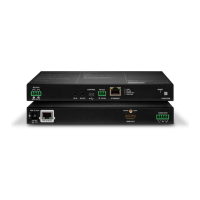
Introduction
HDMI-TPS-RX120-HDSR is a TPS receiver with a local HDMI input and a built-in HD video
scaler. Conversion between common formats and frame rates are supported. One common
resolution can be used across a system independently of the connected displays requirement,
which improves general performance.
The connected display receives continuous HDMI signal thanks to the scaler, thus eliminating
annoying warnings and longer interruptions when switching the input signal.
Compatible Devices
The receiver is compatible with other Lightware TPS devices, TPS and TPS2 output boards,
as well as third-party HDBaseT-extenders, displays, but not compatible with the phased out
TPS-90 extenders.
The product is compatible with any HDBaseT
TM
third party devices.
HDBaseT
TM
and the HDBaseT Alliance logo are trademarks of the HDBaseT Alliance.
Box Contents
Optional Accessory
The following accessory can be purchased separately:
Powering Options
The receiver cannot be powered remotely, always use the supplied power adaptor.
Warranty is void if damage occurs due to use of a different power source.
Locking DC Connector
The DC connector has a small latch which helps to avoid
an unwanted power disconnection – push the plug until it
stops. Be careful when disconnecting the DC plug from the
connector, do not pull it by grabbing the cable, always grab the
moveable plastic angular housing as indicated in the gure.
Receiver unit External Power Supply
Unit (24V / 2.7A)
Remote Control unit
with AAA battery (2x)
IEC power cable
Safety and Warranty info,
Quick Start Guide
1
USB Port The port is used to perform a rmware upgrade only.
2
IR Sensor Receiving the IR signals from the supplied remote controller.
3
HDMI Output Connect an HDMI cable between the receiver and the
display device.
4
HDMI Input Connect an HDMI cable between the HDMI source and
the receiver unit.
5
Input LED Green: TPS input is switched to the output.
Red: HDMI input is switched to the output.
6
Front Panel
Buttons
The buttons can be used for OSD menu navigation and fast
output format change (see the details below).
1
Input selector
2
Exit from the current menu/parameter
3
OK button to save the actual setting
4
Reserved
5
Displaying the OSD menu
6
Menu navigation buttons
7
Reserved
1
Power LED If the LED lights, the device is powered and ready to use.
2
DC 24V Input 24V DC input for local power supply.
3
RS-232 Port Local RS-232 port for bidirectional serial data
communication; see the RS-232 Communication section.
4
Ethernet The Ethernet data is passed through the device between
the Ethernet and the TPS port.
5
IR Ports IR input/output connectors (3.5 mm Jack).
6
TPS Input TPS input port for connecting a compatible device.
Batteries shall not be exposed to excessive heat
such as sunshine, re or the like.
Front Panel Buttons
MENU Button
Displaying/hiding the OSD menu (HDMI output).
Button
Moving left in the main menu, moving up in a submenu, or decreasing the value of a
parameter.
Toggle the input ports: when the OSD is not displayed, the other input can be selected.
Button
Moving right in the main menu, moving down in a submenu, or increasing the value of a
parameter.
Enter Button
Selecting a menu/submenu item, or saving the value of a parameter.
Button Combinations
and Enter: changing the output resolution to 1920x1080p60 (Full HD) immediately.
and Enter: changing the output resolution to 1024x768p60 (XGA) immediately.
Front View
Mounting Options
The receiver can be mounted by the optional VESA100 Mounting adapter (please contact
sales@lightware.com). See the below example about the application:
Two mounting holes can be found at the bottom of the receiver at each side, the Mounting
adapter can be xed as indicated. The other two holes of the plate can be xed to a VESA-
mounting compatible device (e.g. rear panel of an HDTV).
The VESA100 Mounting adapter can be used to x the receiver e.g. under the desk.
Connecting Steps Remote Control Unit (Optional Accessory)
Bi-directional Pass-through Data Lines
The direction of the video extension is xed from the transmitter side towards to the receiver
but the pass-through data lines are bi-directional. Thus, RS-232, IR, Ethernet source and sink
devices can be connected either to the TX or to the RX and the signal is transmitted to the
other extender.
SERIAL
ETHERNET
INFRA #1
INFRA #2
TX
RXTX
2
Tx data
3
Rx data
5
Ground
Installing the AAA Batteries
Pay attention to the polarity of the batteries as
shown in the gure.
IR Input IR Output
1
IR signal Power
2
Power IR signal
3
Ground Ground
Rear View
About the IR Extension
The IR input and output ports receives/sends baseband IR signal, no modulation/demodulation
is done. These ports are suitable for wired IR connections mostly.
IR Port Pinout (Applicable Plugs)
The IR Transmitter and Receiver units supplied with other Lightware devices cannot
be connected to the receiver directly.
RS-232 Communication
The serial data coming from the TPS line is passed through to the RS-232 port and vice versa.
If the incoming command is known by the receiver, it will be processed. Please note that in
such cases the response from the receiver will be sent to the sender only. E.g. if a command is
sent from the local RS-232 port, the response would not be sent over the TPS line but appear
only at the local RS-232 port.
RS-232 Port Pinout