Quick Start Guide
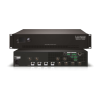
MMX6x2-HT200
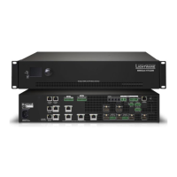
MMX6x2-HT210
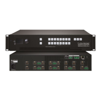
MMX6x2-HT220
Further information
The document is valid with the following rmware version: 1.1.0
The User’s manual of this appliance is available on www.lightware.eu.
See the Downloads section on the website of the product.
Contact us
sales@lightware.eu
+36 1 255 3800
support@lightware.eu
+36 1 255 3810
Lightware Visual Engineering LLC.
Peterdy 15, Budapest H-1071, Hungary
Doc. ver.: 1.0
19200028
The parameters are displayed in two modes on the LCD as follows:
In Display mode the value cannot be changed; the up and down buttons can be used to
step between the submenu items. In Edit mode the values can be changed with the up and
down buttons. Select the desired parameter and press enter to select the Edit mode. After
the value is set and stored, the LCD mode is switched back to Display mode.
1
Output lock Lock and protect one or more outputs.
2
Control lock Disables or enables front panel operations. Red light
means the switching and function buttons are disabled.
3
Destinations Buttons to select an output or to see the state of an output.
4
Sources Buttons to select an input, to select a preset number or to
view the state of the selected input port.
5
Function buttons Switching between working modes (Take / Autotake) and
perform Preset operations.
Important safety instructions
Please read and keep the information in the attached safety instructions supplied with the
product before starting using the device.
Introduction
Lightware’s MMX6x2-HT family responds to a need of a practical standalone matrix switcher
specically designed for meeting room and classroom environments. The agship of the
series is the MMX6x2-HT220 matrix with 6 video inputs and 4 video outputs. The unit handles
4K video formats and 3D signals while it’s fully HDCP compliant. The device has 4 audio input
connectors for audio insertion and 2 audio outputs for de-embedding purposes.
Box contents
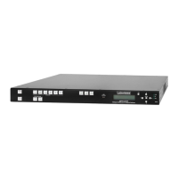
Front view
MMX6x2 matrix LAN cross-link cable,
CAT5e type, 3 m length
IEC power cable
CONTROL LOCK
If the button illuminates in red the switching- and function buttons are disabled.
Press and hold the Control lock button for three seconds to toggle the state.
When the front panel buttons are locked, remote control (RS-232, USB,
Ethernet) is still available.
LCD menu - navigation
Front panel LCD has 2 lines and 16 characters in each line. The name of the menu item is
always displayed in the rst line.
Edit mode
¹IP Address:
192.168.000.09½
¹IP Address: »
192.168.000.095
Display mode
(up)
toggle between menu items
(right)
move the cursor
(down)
toggle between menu items
(enter)
execute changes or enter
(left)
move the cursor or step back
to previous menu
(escape)
step back to previous menu
and/or cancel the operation
Phoenix combicon
3-pole connector
Phoenix combicon
5-pole connector
TPS matrix concept
MMX6x2-HT is the rst stand-alone matrix switcher with HDBaseT
TM
(TPS) technology
in Lightware’s product range. The matrix gives the possibility to route many kinds of signal
formats including TPS and other available interfaces.
TPS working modes
The following TPS modes are dened in the matrix:
Auto: The TPS mode is determined automatically.
HDBaseT: Ideal for high resolution signals up to 4K, maximum 100 m cable length.
Long reach: Ideal for big distances up to 1080p@60Hz.
LPPF1*: Only RS-232 signal is transmitted (at 9600 baud).
LPPF2*: Only RS-232 (at 9600 baud) and Ethernet signal are transmitted.
* LPPF: Low Power Partial Functionality
Safety and warranty info,
Quick Start Guide
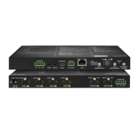
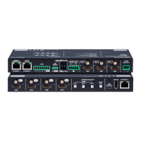
Rear view (MMX6x2-HT220)
1
AC connector Standard IEC connector accepting 100-240 V, 50 or 60 Hz.
2
On / Off switch The matrix can be switched on/off by the switch.
3
RS-232 port 3-pole Phoenix connector for RS-232 serial port.
4
LAN RJ45 connector to control the matrix via LAN/Ethernet.
5
TPS Ethernet RJ45 connector to supply Ethernet for the TPS lines.
6
TPS input ports RJ45 connector for incoming TPS signal; PoE-compliant.
7
HDMI input ports HDMI input ports for sources. Applied cable shall not be
more than 20 m (22AWG) when signal resolution is 4K.
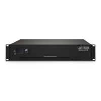
Mounting options
M4x8 size is the longest allowed screw for xing the ears to the housing. Longer
screw may touch internal parts.
Mounting as a standard rack installation - with front rack ears
Two rack ears are supplied with the product, which
are xed on left and right side as shown in the picture.
The default position allows mounting the device as a
standard rack unit installation.
Under-desk mounting - with front and rack ears
Two rack ears supplied with the product; the other
two rack ears can be purchased separately.
Please do the following steps:
1. Release and remove the xing screws of both
rack ears on the matrix.
2. Rotate the rack ears by 90° to the desired
direction.
3. Insert the screws into the holes and x the front ears to the matrix.
4. Fix the two other rear ears (not supplied with the product) by the screws on both sides.
5. Fix the matrix by the rack ears to the desired surface (screws not supplied).
6
USB control USB connector for local control functions (e.g. Lightware
Device Controller software).
7
Display 2x16 character LCD display for menu operations.
8
Menu navigation Up, down, left, right, enter and escape buttons.
9
Reset Reboots the matrix (the same as disconnecting from the
power source and reconnecting again).
q
Status LEDs Blinking CPU LIVE LED indicates normal operation; DC
voltage indicators for internal DC power voltages.
8
Audio input ports 5-pole Phoenix connector for balanced analog audio input.
9
TPS output ports RJ45 connector for outgoing TPS signal. PoE-compliant.
HDMI and TPS output ports are mirrored: the same Audio /
Video content is switched on the given two ports.
q
Audio output
ports
5-pole Phoenix connector for balanced analog audio; the
signal is mirrored from the given TPS/HDMI output port.
w
HDMI output
ports
Connect an HDMI cable between the sink and the matrix.
HDMI and TPS output ports are mirrored: the same Audio /
Video content is switched on the given two ports.
Compatible devices
The matrix is compatible with other Lightware TPS devices, matrix boards, third-party
HDBaseT-extenders, displays, but not compatible with the TPS-90 extenders.
Remote powering (PoE)
The matrix is PoE-compatible (in accordance with IEEE 802.3af standard) and able to send
remote power to connected TPS devices via the TPS connection (through the CATx cable).
No local power adaptor is required for the connected PoE-compatible TPS extender. The PoE
feature is enabled on TPS ports as factory default.
The remote power feature of TPS-95 extenders is not PoE-compatible. Thus, TPS-95
series cannot be powered remotely by the MMX6x2 matrices. If an RX95 or TX95 is
connected to the matrix, make sure that the remote power jumper of the extender is
removed or set to 'Remote power disabled' position.
Powering on
Connect the power cord to the AC input connector. Switch on the matrix by the power switch
on the rear panel. During the initial self-test and loading of the latest settings Booting…
appears on the LCD screen. After the self-test, the router reloads its last conguration and it
is ready to use. In case of hardware failure, an error message is displayed.
After switching ON, the router reloads the latest settings that were used before it was
turned off. The router has an internal emergency memory that stores all current settings and
ties congurations. This memory is independent from presets and invisible for the user. This
built-in feature helps the system to be ready immediately in case of power failure or accidental
power down.
The front panel of the three models look the same.
MMX6x2-HT200 does not contain TPS output port. MMX6x2-HT210 contains only one
TPS output port.
Mounting - with Mounting bracket V2
Two pieces of Mounting bracket V2 is necessary
which can be purchased separately.
Please do the following steps:
1. Prepare the desk and cut the necessary hole in
the furniture. The frame size is 442 x 43.9 mm
without rack ears.
2. Remove the rack ears and the xing screws
from both sides of the matrix.
3. Insert the screws into the holes and x the mounting bracket to the matrix. Pay attention
to the thickness of the desk and let enough space to the front when xing the brackets.
4. Insert the matrix in the hole and x the bracket by the screws to the furniture.
Ventilation
To ensure the correct ventilation and avoid overheating let enough free space
around the appliance. Do not cover the appliance, let the ventilation holes free on both
sides.
The following picture shows the direction of the airow:
Safety and
warranty
info
Quick
Start
Guide
2 6 7 8 q9541 3
1 2 3 4
5
6 7 8 q w{9
CONTROL
LOCK
INPUT OUTPUT
TPS
HDMI
Ethernet
RS-232
Infrared
Analog
audio
HDMI
+ Ethernet (LAN)
+ RS-232
TPS
HDMI
Ethernet
RS-232
Infrared
Analog
audio
HDMI