7 8
Safety and
Warranty
Info
Quick
Start
Guide
DP HDMI1 DVI-D
Autoselect
HDMI2
Important Safety Instructions
Please read the supplied safety instruction document before using the product and keep it
available for future reference.
The transmitter is a Class 3R laser product. Caution! Invisible Class 3R laser
radiation! Avoid exposure to the beam!
Introduction
Thank you for choosing Lightware SW4-OPT-TX240RAK transmitter. The product is a multi-
mode single ber extender with bidirectional RS-232 extension. The device transmits DP /
HDMI / DVI digital video signals up to 4K resolution, 3D and HDCP compliant and is able to
embed analog audio from 3.5mm TRS (Jack) or 5-pole balanced Phoenix type ports. The
transmitter is built with USB KVM function. The device features Pixel Accurate Reclocking,
a Lightware technology to eliminate jitter and skew generated by low quality sources and
multiple daisy-chained devices.
Box Contents
Transmitter unit 5V DC adaptor with
interchangeable plugs
Phoenix Combicon 3-pole
connector
Phoenix Combicon 5-pole
connector
Safety and warranty info,
Quick Start Guide
Phoenix Combicon 8-pole
connector
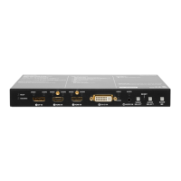
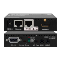
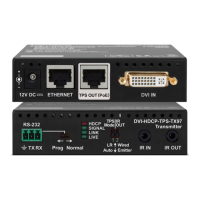
Rear View
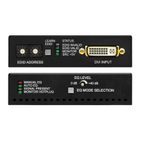
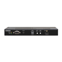
Front View
1
SC ber output Connect a multi-mode single ber optical cable between the
receiver and the transmitter.
2
Audio2 input 5-pole Phoenix connector for balanced analog audio input.
3
HDMI output Connect an HDMI cable between the transmitter and the
display device.
4
Ethernet RJ45 connector to remote control the transmitter via LAN
network.
5
Status LEDs LEDs give feedback about actual status of unit and
connection signals.
6
GPIO 8-pole Phoenix connector for congurable general purpose
input/output ports.
7
RS-232 3-pole Phoenix connector for serial communication.
8
5V DC input Connect the output of the supplied 5V DC power adaptor.
Rear Panel LEDs
LIVE
OFF: device is not powered.
BLINKING (green): device is powered and operational.
BLINKING (red): alert detected.
BLINKING (yellow): rmware upgrade mode, device is in bootload mode.
ON (yellow): device is powered but no operation.
LASER ACTIVE
ON (red): laser transmission is enabled.
FIBER LINK
OFF: no ber link between transmitter and receiver.
ON: ber link is established.
RS-232
OFF: RS-232 ports (local and link) are in Pass-through mode.
BLINKING: Command injection mode is active.
ON: RS-232 ports (local and link) are in Control mode.
Connecting Steps
Mounting
To mount the transmitter Lightware supplies optional accessories for different usage. There
are two kinds of mounting kits with similar xing method. The transmitter has two mounting
holes with inner thread on the bottom side. Fasten the device by the screws enclosed to the
accessory.
The Under-desk double mounting kit makes it easy to mount a single device on any at
surface, e.g. furniture. 1U high rack shelf provides mounting holes for fastening two half-rack
or four quarter-rack sized units. Pocket-sized devices can also be fastened on the shelf. To
order mounting accessories please contact sales@lightware.com.
The transmitter is half-rack sized.
Under-desk double mounting kit 1U high rack shelf
Front Panel LEDs
Video Source LEDs
OFF: video source is not selected.
BLINKING: video source is selected but no signal is detected.
ON: video source is selected and active.
Audio Source LEDs
OFF: audio source is not selected.
BLINKING: audio source is selected but no signal is detected (digital inputs only).
ON: (with short pause): audio source is selected and the port is active but not embedded
to the output video stream (DVI output mode).
ON: (continuously): audio source is selected, the port is active and the audio is embedded
to the output video stream (HDMI output mode).
When Autoselect is enabled and video signal is not present at all, video LEDs blink.
HDCP LED
OFF: video output signal is not encrypted with HDCP.
ON: video output signal is encrypted with HDCP.
Autoselect LED
OFF: Autoselect is disabled.
BLINKING: Autoselect function is enabled, searching for signal (the video input LEDs are
also blinking).
ON: Autoselect function is enabled, the active video signal is found (the selected video
input’s LED is also ON).
Connect the power adaptor to the DC input on the transmitter rst, then to the
AC power socket.
Video/Audio Input Selection
Desired video/audio input can be selected by the VIDEO / AUDIO SELECT buttons on the
front panel. The selection order of the video inputs is the following:
Front Panel Button Functions
Video input switching: Press the VIDEO SELECT button.
Audio input switching: Press the AUDIO SELECT button.
Lock/unlock buttons: Press the AUDIO SELECT and the SHOW ME buttons together.
USB LED
OFF: USB is disconnected or there is no USB data transfer over the port.
ON (green): USB KVM: composite mode is active.
ON (yellow): USB KVM: transparent mode is active.
1
HDCP status
LED
LED shows the actual HDCP status of the video output.
2
USB port USB interface for USB KVM function, rmware upgrade, and
LDC software control purposes.
3
DisplayPort
input
Connect a DisplayPort cable between the DisplayPort source
and the transmitter unit.
4
HDMI input
ports
Connect an HDMI cable between the HDMI source and the
transmitter unit.
5
DVI-D input DVI-I connector for HDMI or DVI-D signal.
6
Audio1 input 3.5mm Jack connector for unbalanced analog audio input signal.
7
Video select Button for switching between video sources.
8
Autoselect
status LED
LED gives feedback about the actual status of the video
autoselect function.
9
Reset button Pushing the button reboots the unit.
q
Audio select
button
Button for switching between audio sources.
w
Audio2
status LED
LED gives feedback about actual connection status of Audio2
input port (on the rear side of device)
e
Show Me
button
Special functions are available with this button (bootload mode,
DHCP, restore factory default settings).