Wiring Guide for RS-232 Data Transmission
UMX-TPS-TX100 transmitters are built with 3-pole Phoenix connector. See the below
examples of connecting to a DCE (Data Circuit-terminating Equipment) or a DTE (Data
Terminal Equipment) type device:
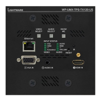
Port Diagram (of TX140 models)
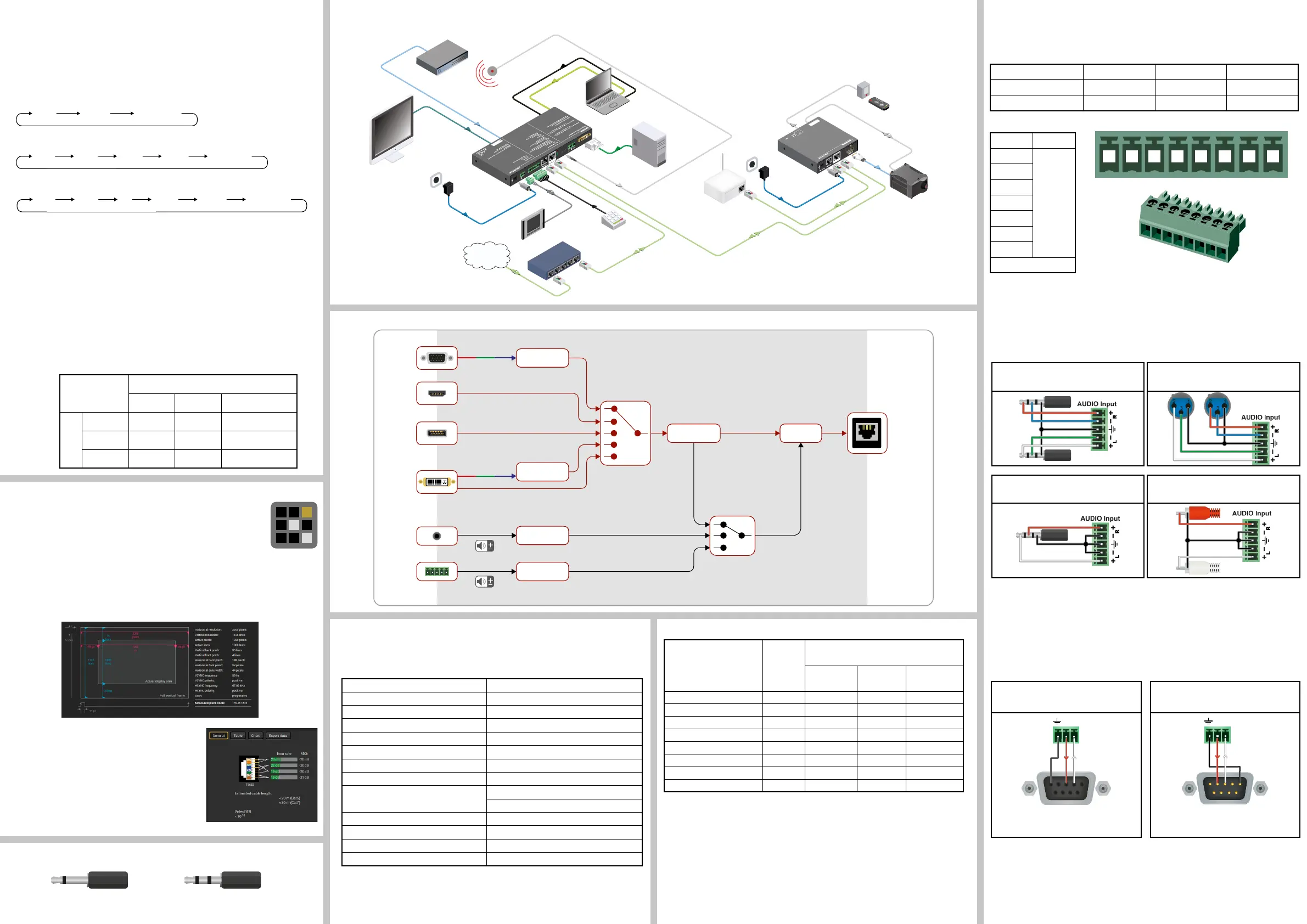
Typical Application
Software Control – Using Lightware Device Controller (LDC)
The device can be controlled from a computer through the Ethernet port
using Lightware Device Controller. Please download the application from
www.lightware.com, install on a Windows PC or a macOS and connect to the
device via the Ethernet port. LDC software contains many useful built-in tools
which can be used for signal analysis like the followings:
Frame Detector
Lightware’s Frame Detector function works like an input signal analyzer and makes possible
to determine the exact video format that is sent by the source, thus helps to identify many
problems (e.g. timing parameter difference).
TPS Cable Diagnostics
The estimated cable length and the quality of the link are
measured periodically and the diagnostic window shows
the values in real-time. If the green bars hit the rst line
in the middle they turn into red. It means the number of
the errors – during the extension – is higher than the
recommended one. The link might be alive but recovering
of the received data is not guaranteed.
Restore Factory Default Settings
1. Keep the Show me button pressed for 10 seconds; after 5 seconds front panel LEDs
start to blink but keep the buttons pressed; the LEDs start to blink faster 5 seconds later.
2. Release the button, then press it 3 times quickly; factory default settings are restored:
Maximum Extension Distances
Resolution
Pixel
clock rate
Cable lengths
(Auto / Long reach TPS mode)
CAT5e
AWG24
CAT7
AWG26
CAT7
AWG23
1024x768@60Hz 65 MHz 100 m / 130 m* 90 m / 120 m* 120 m / 170 m*
1280x720p@60Hz 73.8 MHz 100 m / 130 m* 90 m / 120 m* 120 m / 170 m*
1920x1080p@60Hz (24bpp) 148.5 MHz 100 m / 130 m* 90 m / 120 m* 120 m / 170 m*
1920x1200@60Hz 152.9 MHz 100 m / NA 90 m / NA 120 m / NA
1600x1200@60Hz 162 MHz 100 m / NA 90 m / NA 120 m / NA
1920x1080@60Hz (36bpp) 223 MHz 70 m / NA 70 m / NA 100 m / NA
3840x2160@30Hz UHD ** 297 MHz 70 m / NA 70 m / NA 100 m / NA
4096x2160@30Hz 4K ** 297 MHz 70 m / NA 70 m / NA 100 m / NA
* Long reach TPS mode supports pixel clock frequencies up to 148.5 MHz.
** If 4K video is selected to the output, analog audio cannot be embedded to the video stream
due to the capabilities of the video IC, thus the original audio stream is transmitted.
Above values are valid when the transmitter is powered by a local adaptor; distances may
decrease depending on the powering mode (local or remote) and cable quality. To specify
the accurate extension distances, please also check the documentation of the connected
HDBaseT-compatible device.
CAT7 SFTP AWG23 cable is always recommended.
Setting a Dynamic IP Address
1. Keep the Show me button pressed for 5 seconds; all front panel LEDs start to blink.
2. Release the button, then press it 3 times quickly. DHCP is now enabled.
IP address (fix) 192.168.0.100
Subnet mask 255.255.255.0
Static gateway 192.168.0.1
DHCP disabled
TCP/IP port nr. LW2 / LW3 10001 / 6107
Crosspoint setting (Audio / Video) Audio 1 (Audio) / VGA input
Autoselect disabled
Output TPS mode Auto
Emulated EDID Analog ports: F89
Digital ports: dynamic
RS-232 mode Pass-through
RS-232 control protocol LW2
RS-232 port setting 57600 BAUD, 8, N, 1
Command injection port (local / link) 8001 / 8002
Front Panel Button Functions
Lock/Unlock Buttons
Press the AUDIO SELECT and the SHOW ME together.
Video Input Selection
The desired video input can be selected by the VIDEO SELECT button on the front panel. The
selection order of the inputs depend on the model as follows:
TX120 models:
TX130 models:
TX140 / TX140-Plus models:
The input can be also selected by using LDC (Lightware Device Controller), sending a protocol
command, or using Autoselect.
Audio Input Selection
The desired audio input can be selected by the Audio select button on the front panel. The
selection order of the inputs depend on the model. The input can be also selected by using
LDC (Lightware Device Controller), sending a protocol command, or using Autoselect.
Autoselect
VGA
HDMI DVI-D DVI-A
Autoselect
VGA
HDMI DP DVI-A DVI-D
If 4K video is selected to the output, analog audio cannot be embedded to the video stream
due to the capabilities of the video IC, thus the original audio stream will be transmitted.
Cross Audio-embedding
The video and audio inputs can be combined with limitations. Below table contains the allowed
connections:
Audio source
HDMI DP Analog Audio Input
Video source
HDMI
-
DP -
VGA - -
Types of IR connectors (1/8” TRS / TS)
2 pole, 1 ring: IR transmitter 3 pole, 2 rings: IR receiver
For more information about the cable wiring see the user’s manual of the device or the Cable
Wiring Guide on our website www.lightware.com/support/guides-and-white-papers.
GPIO - General Purpose Input/Output Ports
The device has seven GPIO pins which operate at TTL digital signal levels and can be set to
high or low level (Push-Pull). The direction of the pins can be input or output (adjustable). The
signal levels are the following:
Input voltage (V) Output voltage (V) Max. current (mA)
Logical low level 0 - 0.8 0 - 0.5 30
Logical high level 2 -5 4.5 - 5 18
GPIO connector and plug pin assignment
Pin nr. Signal
1
Congurable
2
3
4
5
6
7
Ground
The total available current of the controller is 180 mA.
Audio Cable Wiring Guide
UMX-TPS-TX140 / TX140-Plus transmitters are built with 5-pole Phoenix input connector. See
below a few example of the most common assembling cases.
For more information about audio cable wiring see the user’s manual of the device or the
Wiring Guide on our website www.lightware.com/support/guides-and-white-papers.
From balanced output to balanced input
2x6.3 (1/4”) TRS - Phoenix
From balanced output to balanced input
2xXLR - Phoenix
From unbalanced output to balanced input
3.5 (1/8”) TRS - Phoenix
From unbalanced output to balanced input
2xRCA - Phoenix
PIN: 2.1mm
GPIO
RS-232
TX RX
AUDIO2 IN
DVI-I IN
IR IN IR OUT
LIVE
RS-232
SRVC
LINK
12V 1A DC
Touch panel
Button panel
PC
DVI
VGA
analog
audio
IR
Ethernet
switch
UMX-TPS-TX140
Blu-ray player
MAC
RS-232
Laptop
12V DC power
adaptor
12V DC
power
adaptor
IR emitter
WiFi
access
IR
RS-232
HDMI
TPS connection
CATx up to 170m
HDMI-TPS-RX97
IR detector
HD Projector
HDMI
DP
Internet
LAN
LAN
LAN
Sn
:
Made in EU, Hungary
RoHS
Ethernet 10/100
Bidirectional IR
Bidirectional RS-232
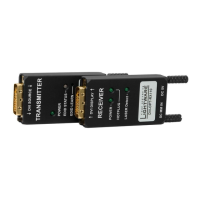
TTPPSS LL
oonngg
DDiissttaa
nncc
ee
TTrraa
nn
ssmm
iitttteerr
HDMI, 3D, 4K supported
For best performance use
AWG23
CAT6 or CAT7 SFTP
cable
PIN: 2mm
12V 1A
DC
H
D
M
I
--T
P
S
--
T
X
9
7
Device can be remote powered over TPS link with PoE
(IEEE 802.3af)
TP
S
O
UT
PoE
( )
HDMI in
VGA in
DP in
DVI in
Analog
audio in 1
Analog
audio in 2
Analog audio
Analog video
Digital video + Digital audio
Analog video
Analog audio
Digital audio
A/D converter
Digital audio
5:1 digital
A/V switch
Digital video + Digital audio
Digital video + Digital audio
Digital
audio
Digital video
A/D converter
Embedder
A/D converter
A/D converter
3:1 digital
audio switch
De-embedder
Digital
audio
TPS OUT (PoE)
TPS out
Lightware device and a DCE
D-SUB 9 – Phoenix
Lightware device and a DTE
D-SUB 9 – Phoenix
1
6
9
5
2: TX data transmit
3: RX data receive
1
6
9
5
2: TX data receive
3: RX data transmit
1 2 3 4 5 6 7 8
 Loading...