2 ©2013 2GIG Technologies Inc. All Rights Reserved.
SELECTING A LOCATION FOR THE KEYPAD
1 MakesurethatACPowerisavailablenearby.
TIP: Becarefulofstuds,electricalwiresandpipesinthewall.
2 Usethekeypad’sbackcoverasatemplatetomarkthescrewholes
withapencilandthepower(wiring)accesshole.
3 Useadrywallsawtocutthewiringhole.
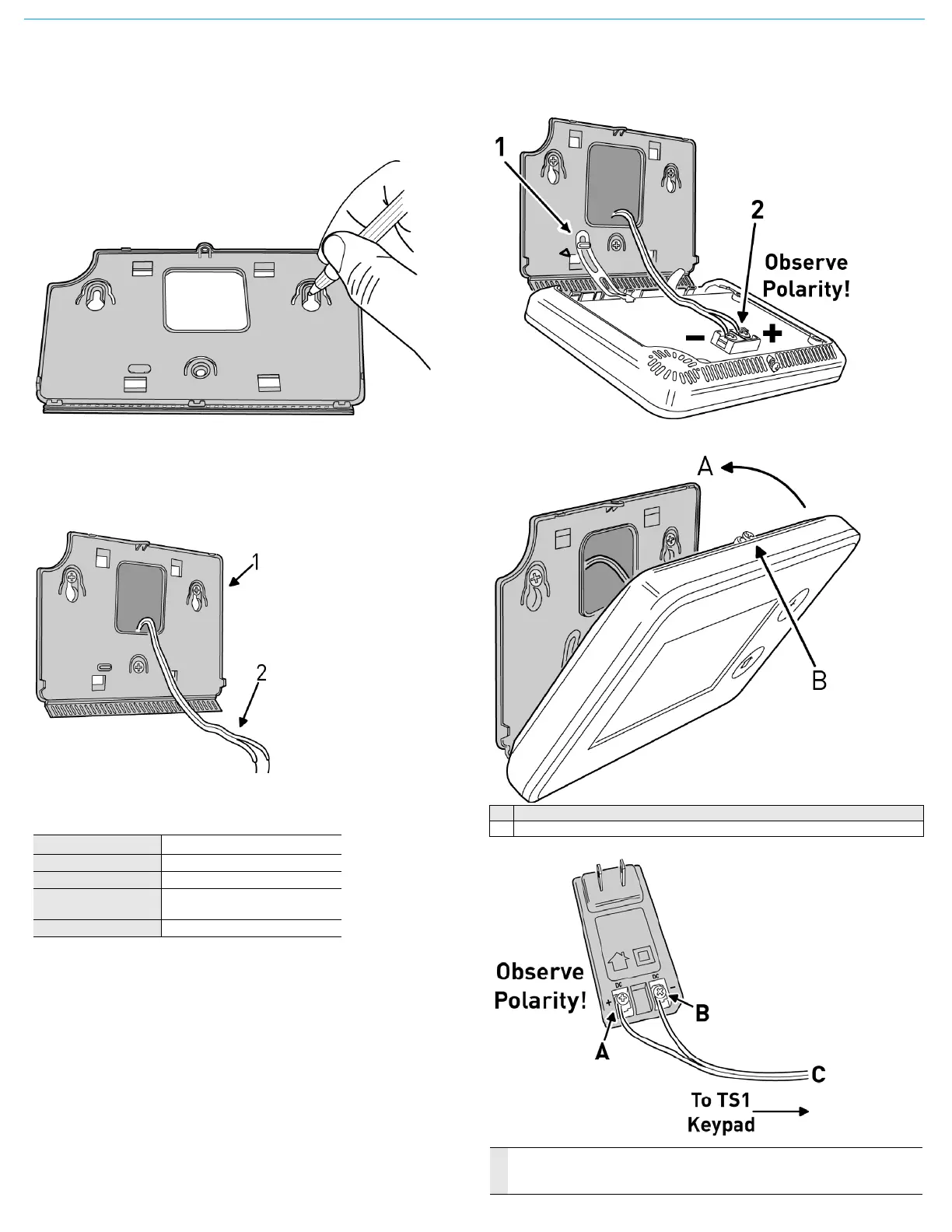
Mounting the Keypad
1 Usethe3screwsandanchorsthataresuppliedtoattachthe
mountingplatetothewall.
2 Route18AWGwirebetweenthekeypadandth elocationofthe
powersupply.
Wire Size and Length
Toensureproperoperation,DoNotexceedthefollowingmaximum
lengthforthewiresizeinstalled:
Toensurethattheappropriatewiresizeandlengthareinstalled,
measurethevoltagebetweenthepowerconnectionterminalsatthe
backofthecontrolpanel.Thevoltagemeasuredmustnotfallbelow11
voltsDCornuisance“A
CPowerLoss”messagesmaybedisplayedand
reported.
NOTE: IntheUnitedStates,wiringroutedinsidewalls,ceilings,and
floorsmustcomplywithrequirementsoftheNationalElectrical
Code,ANSI/NFPA70andlocalbuildingcodes.Forwiringfrom
theoutputofthe2GIGclassIIpowersupply,wiringratedCL2,
CL2X,CL2R,orPLTCisrecommendedtosatisfythese
requirements.Ifthiswir
ingisinstalledinanairplenum(space
usedforenvironmentalairexchange)itmustberatedCL2P
(plenumrated).
Connect the Power Wires to the Keypad
1 Re‐connectthehangingstrap.
2 Use#6insulatedspadeterminals(notsupplied)toconnectwires
fromthepowersupplytothekeypad.
3 Closethekeypad.
4 Connectthepowerwirestothepowersupply.
Wire Size Maximum Length
22AWG 55feet(16.8meters)
20AWG 85feet(25.9meters
22AWG2‐pairs
(19AWGequivalent)
110feet(33.5meters)
18AWG 135feet(41.1meters)
A Snap case closed.
B Tighten case screw.
A Left Terminal 14 VDC(+)
B Right Terminal 14 VDC (-)
C 18 AWG/2-Conductor
 Loading...