Do you have a question about the Linear AE-1000 and is the answer not in the manual?
| Brand | Linear |
|---|---|
| Model | AE-1000 |
| Category | Intercom System |
| Language | English |
High-sensitivity receiver for wireless transmitters.
Four relays with 3-amp @ 24-volt rating for access devices.
Inputs to activate access devices for exiting.
Inputs for door position sensing or access inhibit.
Provides audible chirps during keystrokes.
Enables remote access and programming via telephone line.
COM port for direct computer connection.
Allows multiple units to connect for data sharing.
Accessory adds additional inputs and outputs.
Stamps event log data with time and date.
Two inputs for Wiegand format card readers.
Three ports for connecting Linear accessories.
Supports optional camera for video monitoring.
Monitors AC power input and records outages.
System programmable via computer and modem.
Supports up to 20,000 entry codes for access.
Flexible code length for various applications.
Supports up to 10,000 residents in the directory.
Customizable directory number length.
Supports up to 45,600 transmitters for access.
Identifies transmitters by installation.
Supports up to 45,600 cards for access.
Four programmable relay outputs for access control.
Schedule relay activation for up to four time periods.
Validate access within specific time zones.
Select specific days of the week for access.
Schedule holidays for access restriction.
Compatible with obstacle transmitters like MGT.
Stores up to 20,000 system events for record keeping.
Logs deleted cardholders for future identification.
Disables entry code for a programmed time after use.
Four 3-amp relay outputs for access devices like strikes and locks.
Inputs for activating access devices via pushbuttons or loop detectors.
Inputs for door position monitoring or access inhibit functions.
Enables remote programming and control over a phone line.
For direct local programming via a computer's COM port.
Primary keypad for system operation and control.
Provision for a USPS postal lock to activate a relay.
Compatibility with MGT safety edge transmitters.
Flash memory retains data without power.
Uses AccessBase2000 software for system setup.
Supports 12-volt battery for operation during power outages.
Connects multiple units via RS-485 for shared data.
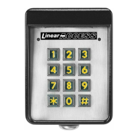
Ports for connecting accessories like keypads and readers.
Accessories connecting via PBUS ports like keypads and receivers.
Accessories connecting via Wiegand inputs like card readers.
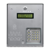
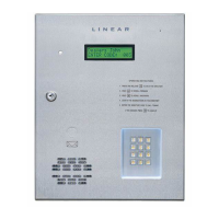
Key external components like display, keypad, microphone, and speaker.
Locations of various connectors for wiring and expansion.
Controls for speaker volume, display contrast, and receiver range.
Terminals for power input and earth ground connection.
Wiring example for electric door strike control.
Wiring example for magnetic door lock control.
Wiring example for gate operator control.
Wiring for door exit request buttons or sensors.
Wiring for door sense contact and gate exit loop sensors.
Considerations for environmental factors during installation.
Adherence to local building codes for access control equipment.
Guidelines for placing the unit near entry points, avoiding vibration.
Specific distance requirements for gate operator installations.
Placement considerations to avoid obstructing traffic lanes.
Wheelchair access requirements for reach and clearances.
Steps to prepare the unit for mounting, including disconnecting wires.
Instructions for mounting the cabinet directly to a wall or flat surface.
Instructions for flush mounting the unit using a trim ring.
Instructions for mounting the unit on a gooseneck pedestal.
Wiring for electric door strikes and magnetic locks.
Wiring for connecting to gate operators.
Wiring for devices that signal an exit request.
Wiring for door sense switches to monitor door status.
Instructions for connecting the power transformer and wiring gauge.
Guidance on optional battery backup and external chargers.
Requirements for proper grounding to ensure safety and performance.
Details on connecting to a computer for programming.
Guidelines for routing and connecting telephone lines.
Specific connection methods using modular connectors or terminals.
Adjustment for receiver sensitivity to optimize range.
Steps to install a U.S. Postal Service lock and microswitch.
Steps to install the CCTV camera and connect video output.
Instructions for connecting PBUS accessories like keypads and readers.
Instructions for connecting Wiegand output devices like card readers.
Wiring configuration using one unit as a network hub.
Wiring configuration for daisy-chaining units in a network.
Adjusting the audio level for the speaker.
Adjusting the display's visibility and contrast.
Adjusting the volume level of system tones.
Function of the button to reboot the system microcontroller.
Description of LED indicators on the main circuit board.
Functionality of the seven pushbuttons on the main circuit board.
How the STATUS/PROGRAM display shows system conditions.
Display codes for various supervisory conditions.
Steps to enter and change system settings via programming.
Process for visitors to gain access using a code.
Process for visitors to gain access using a transmitter.
Process for visitors to call residents for access.
Case dimensions and physical attributes.
Voltage, current, and output/input details.
Frequency, bandwidth, and sensitivity of the radio receiver.
Operating temperature and humidity ranges.
Diagram showing the physical size of the AE-1000 unit.
Diagram showing the dimensions of the optional trim ring.
Steps to diagnose a completely non-functional system.
Checks for issues causing buzzing sound from the speaker.
Steps to diagnose buzzing on the telephone line connection.
Troubleshooting steps for incoming call issues.
Diagnosing why entry codes are not triggering relays.
Steps to troubleshoot non-functional PBUS devices.
Diagnosing keypad access issues.
Troubleshooting resident phone ringing issues.
Diagnosing why transmitters fail to activate relays.
Steps to resolve issues with short transmitter range.