5
lci1.com 574-537-8900 Rev: 02.25.20
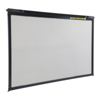
Screen Defender
Installation and Owner’s Manual
(For Aftermarket Applications)
CCD-0003487
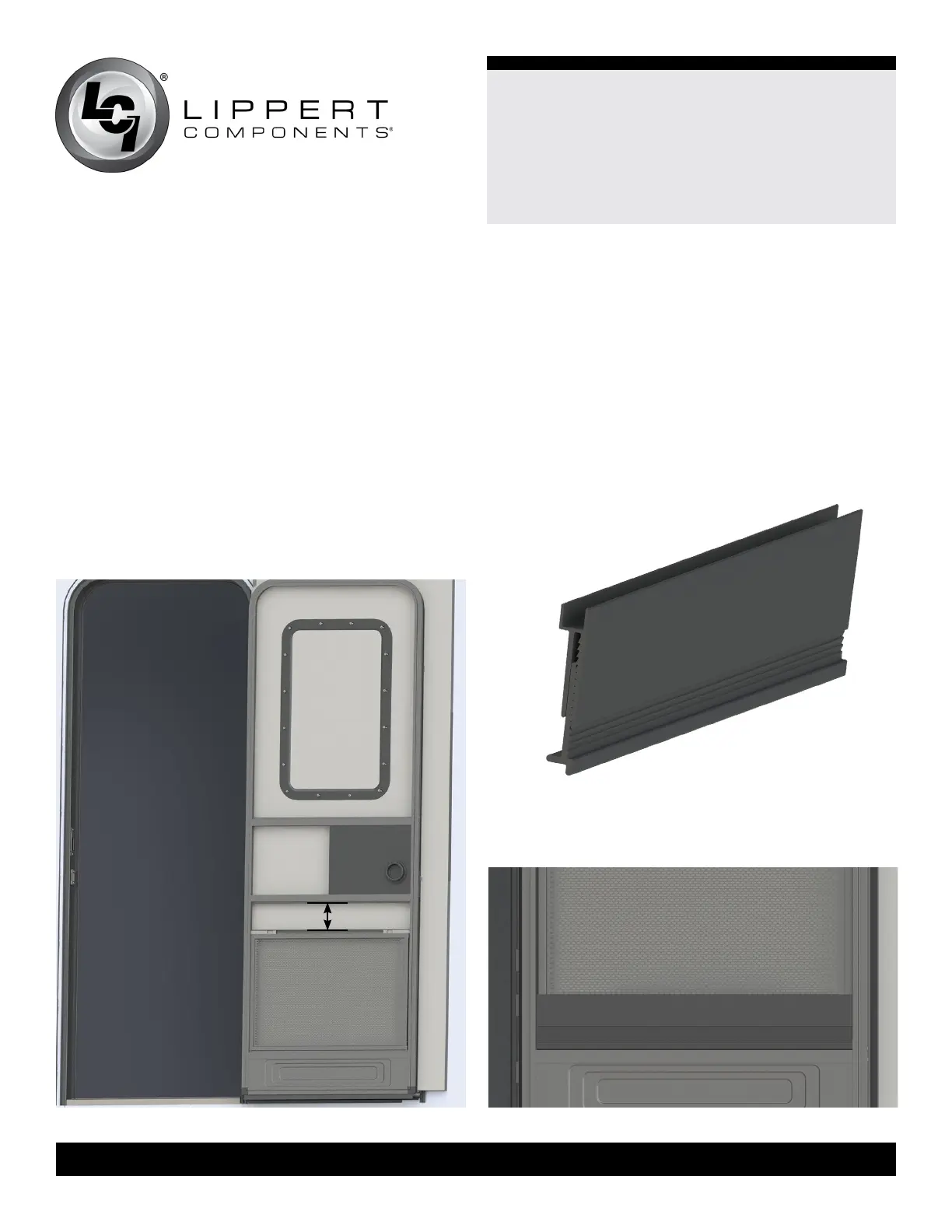
Install Extrusions and Screen Defender.
1. Dry t the Screen Defender into the screen door with the
bottom edge of it resting on the bottom inside edge of the
screen frame (Fig.3).
2. Measure the distance between the top edge of the
Screen Defender and the horizontal frame that makes up
the lower side of the H bar.
NOTE: If a Screen Shot automatic screen door closer is
installed, make sure the measurement taken is below the
Screen Shot and not up to the H bar.
3. If the gap to be lled by the extrusions is less than 2”,
select the short set of extrusions. However, a larger gap
requires the standard set of extrusions.
Fig.3
Fig.4
NOTE: The female and male extrusions from the standard
and short kits can be mixed and matched to achieve
desired results.
NOTE: There is a channel approximately 3/8” deep at the
top of the extrusions where the bottom of the Screen
Defender will be placed. This will extend the size of the gap
accordingly.
4. Press the male and female extrusions together to match
the height of the gap, starting at one end and then pressing
in the middle and then the other end (Fig.4).
5. Place the assembled extrusions on the low frame rail of
the screen door (Fig.5).
Fig.5
gap
 Loading...