1.Please adjust the resolution on DIP SWITCH prior to installation.
(Please refer to )
2.Remove 4 pieces of foot pads on the bottom of the camera by
rotating the foot pads counterclockwise.
*Please keep the foot pads properly after removal and store them for future use.
3.Fix the metal plate A on the machine base with 4 M3 silver screws.
2. Instruction on DIP SWITCH setting
4.Lock the metal plate B on ceiling mounted hanger
*Caution:
(1) Please use the hanger that has obtained UL security approval.
(2) Please reserve the hole for the connecting wires of the camera.
5.Combine the metal plate A and the metal plate B
▼Push the metal plate A up to the ceiling and then to the right to latch
the metal plate B.
▼And then secure with 2 M3 silver screws and 1 M3 black screw.
black
screw
2.2 IR SELECT
2.1 OUTPUT SWITCH
9
8
A
7
B
6
C
5
D
4
E
3
2
F
1
0
21 3
The factory setting for the
resolution is 2160p/59.94
After the IR SELECT is configured,
it can be switched from the Camera
Select on the remote control
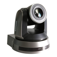
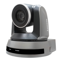
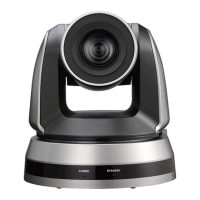
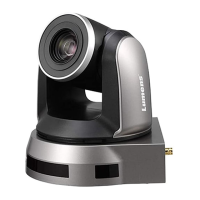
VC-A71SN Quick Installation Guide
metal plate A
www.MyLumens.com
Copyright ©2021 Lumens Digital Optics Inc. All rights reserved.
5100450-50 JUL. 2021
Kensington
Lock Port
Ethernet
Output
Switch
RS-422DC12V
Input
Audio In
IR
SELECT
USB 3.0
RS-232
Output
12G-SDI
Output
RS-232
Input
HDMI 2.0
Output
2. Instruction on DIP SWITCH setting
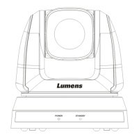
1. A view of the camera's I/O interface
3. Install the camera on the ceiling