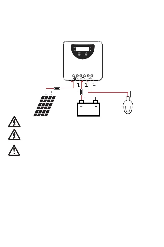
5.3 Connection
We strongly recommend connecting a fuse directly to the battery terminal to protect from any short
circuit in the battery circuit. PV-modules generate current whenever light shines on them. The generated
current is directly proportional to the light intensity. Even low levels of light, will deliver the PV-Modules
no load, full voltage. It is thus utterly advisable to protect PV-modules from any incident light during
installation; Never touch uninsulated cables (ends), only use electric insulated tools, and make sure that
the wire cross section is adequate for the PV module operating currents. Connections must always be
conducted in the sequence as described below
⑤
⑥
①
②
③
④
1st step: Connect loads
Connect the load cable with the correct polarity of the right-hand side pair of terminals on the solar
charge controller (with the lamp symbol). To avoid the presence of any tension on the cable/wires, please
connect these first to the load before connecting them to the charge controller.
2nd step: Connect the battery
Connect the battery cables observing the correct polarity to the center pair of terminals (make sure you
identify the battery marking/symbol on the controller casing!) of the PV charge controller. Pay greatest
attention to polarity. Never, ever invert the plus+ and minus- poles). Should your system be nominal 12
Vdc, make sure the battery voltage is between the 5.0 and 15.5 Vdc voltage range; for 24 Vdc nominal
voltage, the battery voltage should be within the 20.0 to 31.0 Vdc range. Voltages are identifiable when
the controller is set to a lithium battery. If the polarity is correct, the LCD on the controller will begin to
display those.
3rd step: Connect the solar module
When connecting the PV-Module make sure to cover it from incident sun light. Double check the PV-
Module will not exceed the maximum permissible input current of the Charge Controller (please refer to
the section Technical Data). Connect the solar module connection cable to the correct polarity of the left
pair of terminals on the solar charge controller (with the solar module symbol).
4th step: Final work
Tighten all cables connected to the controller and remove all the remains around the controller (leaving a
void of minimum 15 cm).
WARNING: The PV-module/array can produce open-circuit voltages in excess of 100 Vdc
when exposed to sunlight. Pay highest attention to this fact.
WARNING: Risk of explosion! In case the battery's positive and negative terminals or
leads get ever in touch, i.e. short-circuited, a fire or explosion hazard might get triggered.
Always pay maximum when handling batteries and related circuits.
CAUTION: 1. If no temperature sensor is connected to the controller, the battery
temperature value will display the internal temperature.
2.If a power inverter is used the system, directly connect the inverter to the battery.
Do not connect it to the controller's load terminals.
8
 Loading...