5.5 Grounding
Be aware that the negative terminals of controller are interconnected and therefore bear the same
electrical potential. If any grounding is required, always do this on the negative wires/terminals.
CAUTION: For common-negative system, such as motorhome, it is recommended to use a
common-negative controller; but if in a common-negative system, some common-positive
equipment is used, and the positive pole is grounded, the controller may get damaged.
Model
Rated charging
current
Rated
discharging
current
Solar wire
diameter
(mm²/AWG)
Battery wire
diameter
(mm²/AWG)
Load wire
diameter
(mm²/AWG)
MC2010 20A 20A 6/10 6/10 6/10
MC4010 40A 30A 10/8 10/8 10/8
5.4 Wiring Specifications
Wiring and installation methods must comply with national and local electrical code/specifications.
The wiring specifications of the PV-system battery must be selected according to rated currents. Please check
following table for wiring specifications:
!
controller or between the controller and the battery are required, than larger capacity cables must be
used to reduce voltage drop and improve system performance.
The indicated cable/wire sizes are for reference only. If longer runs between the PV array and the
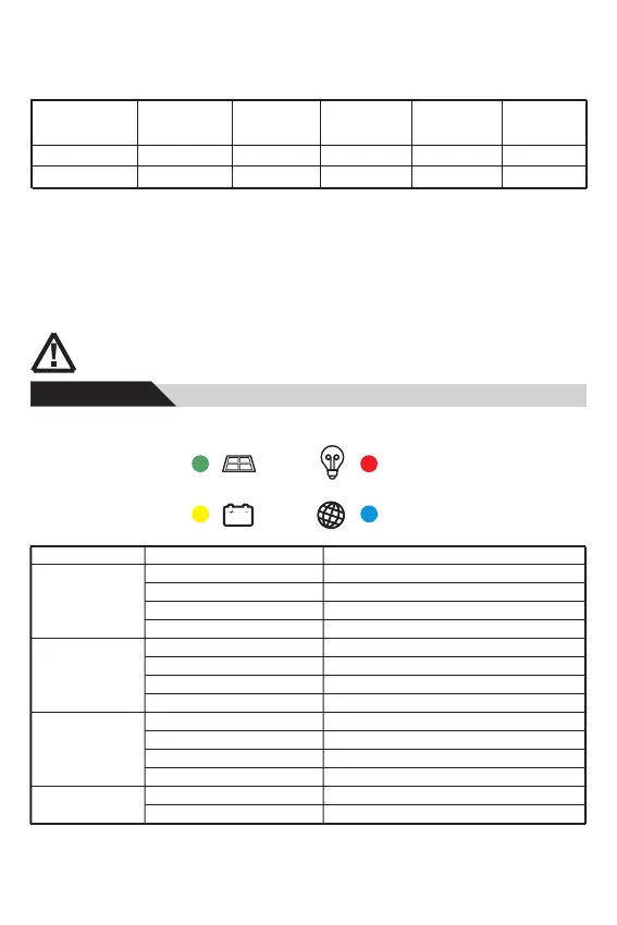
6.1 LED indicator
Status
On
Fast flash(0.1/0.1s)
Flash(0.5/0.5s)
Slow flash(0.5/2s)
On
Off
Fast flash(0.1/0.1s)
Slow flash(0.5/2s)
On
Off
Fast flash(0.1/0.1s)
Slow flash(0.5/2s)
Off
Fast flash(0.1/0.1s)
LED
Green
(PV Panel)
Yellow
(Battery)
Red
(Load)
Blue
(Communication)
Function
Solar panel is connected, no charged.
MPPT charging
Equal or Boost Charging
Float Charging
Battery is normal.
Over voltage protection
Low voltage protection
Battery voltage is low.
Load is on.
Load is off.
Short circuit or over current protection
Over temperature protection
No communication
Normal communication
6, Operation
Solar LED
Battery LED
Load LED
Communication LED
9
 Loading...