Remove all inner side
sections (shaded).
Do not remove outer side
sections.
Important Notes
Please read before installing.
1. CAUTION: To avoid overheating and possible damage to other equipment, do not use to control
receptacles, fluorescent lighting fixtures, or transformer-supplied appliances.
2. When no "ground means" exists within the wallbox, then NEC
® 2008 404.9 exception to (b) allows a
control without a ground connection to be installed as a replacement. For this type of installation, cap or
remove the green ground wire on the control. A control installed under this exception (NEC
® 2008 404.9
exception to (b)) must be provided with a plastic, noncombustible, UL listed wallplate.
3. Set multi-speed fans to their highest setting before installing controls.
4. Do not use control with a fan and light that operate with the same switch.
5. For new installations, wire a test switch before installing the control.
6. Use FSQ-2F and SFSQ-F controls with a ceiling paddle fan only. Use only one ceiling paddle fan
per control.
7. Use FS-5F controls only with fans marked "Suitable for use with solid-state fan-speed controls."
8. Do not wire an FSQ-2F or SFSQ-F in a circuit with a GFCI breaker/receptacle.
9. Controls may feel warm to the touch during normal operation.
10. Install in accordance with all national and local electrical codes.
Multi-Unit Installations
When combining controls in a wallbox, remove all inner side sections before wiring (see below). Use
pliers to bend each side section up and down until it breaks off. FS-5F controls require reduction of their
capacity. Refer to chart below for maximum capacity. FSQ-2F and SFSQ-F controls do not require
capacity reduction.
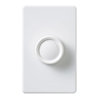
Fan-Speed Controls
FS-5F: 5 A maximum 120 V~ 60 Hz
FSQ-2F: 1.5 A maximum 120 V~ 60 Hz
SFSQ-F: 1.5 A maximum 120 V~ 60 Hz
Disconnect switch wires.
Verify application.
Switch must have two insulated wires connected to two screws and may have
a bare copper or green wire connected to a green screw. Note: Do not connect
to a light fixture.
Ground
(Bare Copper or Green WIre)
Terminal Screws:
Turn screws to loosen.
OR
Backwired:
Insert screwdriver. Pull wire out.
Wiring the control.
• Connect the green wire on the
control to the bare copper or
green ground wire in the wallbox,
if present (see Important Note 2).
• Connect one of the black wires
on the control to either of the
wires removed from the switch.
• Connect the remaining black wire
on the control to the remaining
wire removed from the switch.
Green
Black
Ground
Black
Start screws.
Align dimmer and
tighten screws.
Mount and align control. Install wallplate.
Operation
High Low
Off
Medium
Off
FSQ-2F
Off
High Low
FS-5F
High
Med.
Low
Off
SFSQ-F
Limited Warranty
Lutron will, at its option, repair or replace any unit that is defective in materials or manufacture within one year after purchase. For warranty service,
return unit to place of purchase or mail to Lutron at 7200 Suter Rd., Coopersburg, PA 18036-1299, postage pre-paid.
THIS WARRANTY IS IN LIEU OF ALL OTHER EXPRESS WARRANTIES, AND THE IMPLIED WARRANTY OF MERCHANTABILITY IS LIMITED TO ONE
YEAR FROM PURCHASE. THIS WARRANTY DOES NOT COVER THE COST OF INSTALLATION, REMOVAL OR REINSTALLATION,OR DAMAGE RESULT-
ING FROM MISUSE, ABUSE, OR DAMAGE FROM IMPROPER WIRING OR INSTALLATION. THIS WARRANTY DOES NOT COVER INCIDENTAL OR CON-
SEQUENTIAL DAMAGES. LUTRON'S LIABILITY ON ANY CLAIM FOR DAMAGES ARISING OUT OF OR IN CONNECTION WITH THE MANUFACTURE,
SALE, INSTALLATION, DELIVERY, OR USE OF THE UNIT SHALL NEVER EXCEED THE PURCHASE PRICE OF THE UNIT.
This warranty gives you specific legal rights, and you may have other rights which vary from state to state. Some states do not allow limitations on how
long an implied warranty lasts, so the above limitation may not apply to you. Some states do not allow the exclusion or limitation of incidental or
consequential damages, so the above limitation or exclusion may not apply to you.
This product may be covered by Mexican patent 168,884 and one or more of the following U.S. patents: 4,835,343; 4,835,816; 5,191,971; and
corresponding foreign patents. Lutron is a registered trademark of Lutron Electronics Co., Inc. NEC is a registered trademark of National Fire
Protection Association, Quincy, Massachusetts.
© 2008 Lutron Electronics Co., Inc.
030-1052 030-1052
• For installations involving more than one control in a wallbox, refer to the
section on Multigang Installations before beginning.
Note: Wire location will vary by product. Reference wires by color, not
location.
120 V~
60 Hz
Warning: Verify that power is OFF before proceeding.
Failure to turn power OFF could cause death or
serious injury.
Hot
Black
Black
Ground
Fan
Neutral
Small
Large
Twist wire connector tight.
Be sure no bare wire is exposed.
Small:
Strip insulation 3/8 in (10 mm) for 14 AWG (1.5 mm
2
) wire
Strip insulation 1/2 in (13 mm) for 16 or 18 AWG (1.0 or 0.75
mm
2
) wire.
Use to join one 14 AWG (1.5 mm
2
) supply wire with one 16 or
18 AWG (1.0 or 0.75 mm
2
) control wire.
Large:
Strip insulation 1/2 in (13 mm) for 10, 12 or 14 AWG
(6 , 2.5 or 1.5 mm
2
) wire.
Strip insulation 5/8 in (16 mm) for 16 or
18 AWG (1.0 or 0.75 mm
2
) wire.
Use to join one or two 12 or 14 AWG (2.5 or 1.5 mm
2
) supply wires
with one 10, 12, 14, 16, or 18 AWG control wire (6 mm
2
, 2.5 mm
2
,
1.5 mm
2
, 1.0 mm
2
and 0.75 mm
2
).