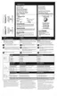
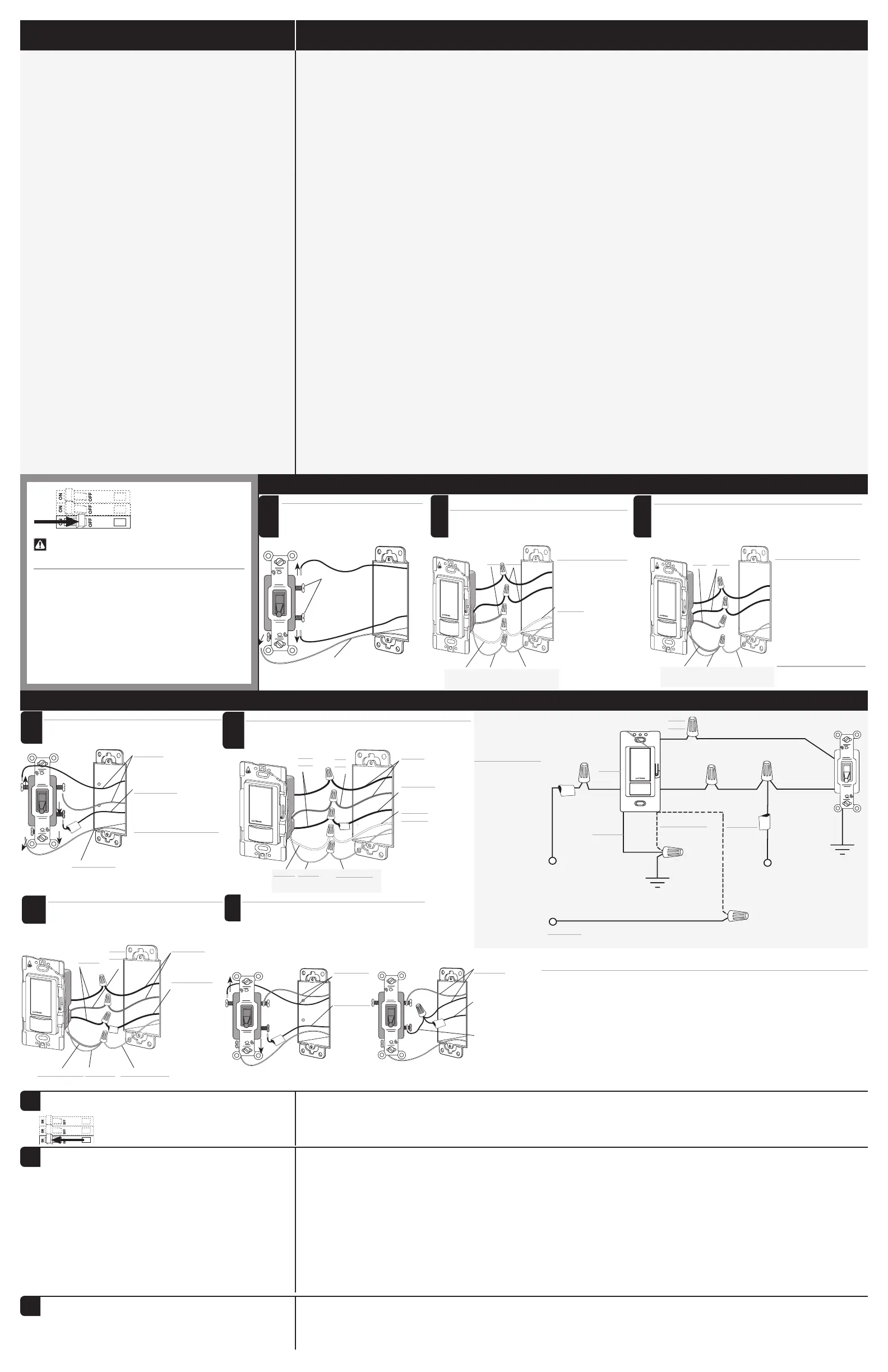
Single-Pole Wiring
Important Notes
Please read before installing.
1
. CAUTION: To reduce the risk of overheating and
possible damage to other equipment, DO NOT use to
control receptacles.
2. Install in accordance with all national and local electrical
codes.
3. A ground connection is required for product to function.
Connect green-sleeved wire to ground only in retrofit and
replacement applications. When neutral connection is
available, remove green sleeve and connect to neutral. If
neither wire is present, consult a licensed electrician.
4. Only one (1) sensing switch can be used in a 3-way/multi-
location application.
5. When using with an accessory switch* for 3-way or multi-
location (more than 2locations) applications.
6. Do not exceed twenty (20) devices at 120 V~ or seven
(7) devices at 277V~ on a single branch circuit.
7. The ability of the sensing switch to detect motion requires
line-of-sight of room occupants. The sensing switch must
have an unobstructed view of the room.
8. Hot objects or moving air currents can affect the
performance of the sensing switch.
9. For indoor use only. Operate between
32 °F and 104°F (0 °C and 40 °C).
10. Clean with a soft damp cloth only. DO NOT use any
chemical cleaners.
11. Once power has been restored, the sensing switch can
be manually turned on or off within the first 30seconds
but will not automatically control the load for the first
2 minutes.
12. Device makes audible click when turning on or off. This is
normal functionality.
13. Load might not respond if 3-way switch is rapidly turned
on/off.
14. MA-AS, MSC-AS, MA-AS-277, or MSC-AS-277 is
required for multi-location applications.
Go to Step 4
5
4
Install sensing switch in wallbox and
restore power
NOTE: Once power has been restored,
the sensing switch will not automatically
control the load for the first 2 minutes.
5
6
Custom Settings (optional)
Leave wallplate off if custom settings are desired.
(See reverse; default settings shown in bold.) To test
sensor coverage, use Test Mode.
5
5
Test the Wiring (3-way only)
!
WARNING! Shock Hazard. May result in serious
injury or death. Turn off power before working
with wiring.
Wait 2 minutes after restoring power before testing.
• If sensing switch does not turn the load off and on,
swap its traveler wires.
• If 3-way switch does not turn the load on when it’s
turned off by the sensing switch, swap its traveler
wires.
5
If no neutral is present, connect green-sleeved wire to ground
2b
5
Remove existing switch
1
Same color
screws
Ground
5
2a
When neutral is present in outlet box; remove green sleeve, connect white wire to neutral
Blue
Black
Ground
BareWhite
Travelers
Tagged wire
5
Remove existing switch at desired location
1
Travelers
Tagged wire
Tag the wire connected to different
color screw.
Ground
Modify existing 3-way switch wiring
3
After
Travelers
Tagged wire
Yellow jumper wire
(included)
Before
Travelers
Tagged wire
Yellow jumper wire
(included)
Tagged wire
(Live or Load)
Tagged wire
(Live or Load)
Blue
Black
Ground
Ground
Bare
Green-sleeved (2b)*
NOTES
Sensing switch may be installed in either location (see Important Note #4).
3-Way Wiring
WARNING! Shock Hazard. May result in
serious injury or death. Turn off power at
circuit breaker before installing the unit.
When neutral is present in outlet box; remove green
sleeve, connect white wire to neutral
NOTE: Cap blue wire for single
pole applications.
Ground
Bare
White
Blue Black
2a
NOTE: Cap blue wire for single
pole applications.
GroundBareGreen-sleeved
Blue Black
5
2b
If no neutral is present, connect green-sleeved wire to ground
Blue
Black
GroundBare
Green-sleeved
Travelers
Tagged wire
Neutral
White (2a)*
OR
Neutral
Neutral
* When neutral is present,
remove green sleeve
and connect white wire
to neutral. If no neutral
available, leave green
sleeve on and connect to
ground.
Learn more about home electrical we have.
 Loading...