Lutron Technical Support Center 1.800.523.9466 24 hrs / 7 days www.lutron.com
Cable tie
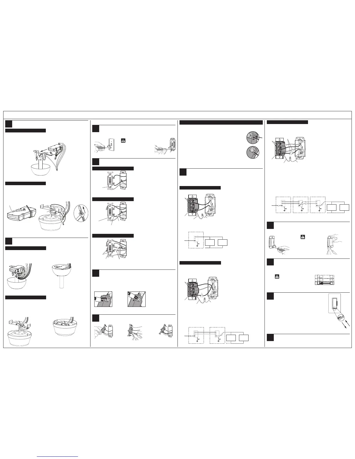
6b - Flush Mount Bracket
• Do not install Canopy Module in ceiling.
• Attach Canopy Module to bracket with a cable tie.
• Ensure cable tie does not come in contact with moving motor parts.
• Install cable tie through notches on Canopy Module. Pull tight and clip excess.
To junction box
6a - Down Rod Bracket
• Do not install Canopy Module in ceiling.
• Slide Canopy Module into the ceiling fan mounting bracket.
To junction box
Remove original wallplate and switch.
• Remove the wallplate and switch mounting screws.
• Carefully remove switches from wall (do not remove wires).
Attach canopy.
Control Installation
7
8
7b - Flush Mount Bracket
• Check all wire connections.
• Tuck the wires into the junction box and/or bracket.
• Ensure wires and/or wire connectors do not come in contact with moving motor parts.
• Attach the canopy enclosure to the fan mounting bracket, taking care not to pinch any wires.
To junction box
To junction box
7a - Down Rod Bracket
• Check all wire connections.
• Tuck the wires into the junction box and/or canopy enclosure.
• Attach the canopy enclosure to the fan mounting bracket, taking care not to pinch any wires.
Danger: Verify power to
each switch is OFF
before proceeding.
Important Note:
Your wall switch may have two wires attached to the same screw (see illustrations below for examples). Tape these
two wires together before disconnecting.When wiring, connect wires to new Controls the same way they were
connected to the switch.
Identify switch wires.
10
One wire in
the push-in
terminal and
one to the
screw.
One
continuous
wire to the
screw.
Disconnect switch wires.
Connect Control(s).
• For installations involving more than one control in a wallbox, refer to Multigang Installations before
beginning.
• Only one Wall Control (MA-FQ4M) can be used with up to 2 Accessory Controls (MA-AFQ4).
Ground
Green wire
Black
screw
Wall Control
Brass
screws
Important Wiring Information
Trim or strip wallbox wires to the length indicated by the strip gauge on the back of the control
OR
12
11
Screw Terminals:
Turn screws to loosen.
Push-in Terminals:
Insert screwdriver.
Pull wire out.
Looped Wire:
Turn screw to loosen.
Wiring the Wall Control (MA-FQ4M):
• Connect either of the wires removed from the switch
to the blackscrew terminal on the Wall Control.
• Connect the remaining wire removed from the switch
to one of the brass screw terminals on the Wall
Control.
• Tighten the remaining brass screw terminal on the
Wall Control. It is not used in a single-pole circuit.
• Use wire connectors to connect the green ground
wire on the Wall Control to the bare copper or green
ground wire in the wallbox (see Important Note 3),
and to cap any unused wires.
Mount Control(s) to wallbox.
• Form wires carefully into the wallbox, mount and align the Control(s).
• Install wallplate(s).
Caution: Do not
overtighten
mounting screws.
13
Align control and
tighten screws.
Start screws.
Insert Canopy Module.
6
15
16
Turn ON power.
• Do not turn on power until Wall Control, Accessory Control(s) and Canopy Module(s) have been
installed and wired.
• Turn power ON at circuit breaker (or replace fuse).
Recommended - Disconnect pull chains.
• Disconnect pull chain extensions to prevent fan speed from being adjusted at the fan(s).
Activate system.
• Pull out the Front Accessible Service Switch (FASS ) at the bottom
of the Wall Control, wait 10 seconds, then push it back in.
• The LEDs will cycle for up to 30 seconds.
• If installing more than one Wall Control/Canopy Module system,
activate one at a time with FASS pushed in on all other systems.
• Accessory Controls do not require activation.
14
Identify the circuit type.
One switch controlling the fan(s).
This switch will be a single-pole. The switch will have
insulated wires connected to two screws of the same color
plus a green ground screw.
Ground
(Bare Copper or
Green Wire)
Two switches controlling the fan(s).
Both switches will be 3-way. Each switch will have
insulated wires connected to three screws plus a green
ground screw. One of these wires is connected to a screw
of a different color (not green) or labeled COMMON. TAG
this wire on both switches to identify when wiring.
Tagged wire
Different colored
screw (Common)
Ground
(Bare Copper or
Green Wire)
Three switches controlling the fan(s).
Two switches will be 3-way and one will be a 4-way.TAG
the two 3-way switches as in the Two-Location diagram
above. The 4-way switch will have insulated wires
connected to four screws plus a green ground screw.TAG
two insulated wires which are connected to same colored
screws.
Tagged wires
Note: Screw
placement may
be different on
your switch.
Same colored
screw (or marked
IN or OUT)
Ground
(Bare Copper or
Green Wire)
9c - Three-Location control
9b - Two-Location control
9a - Single-Location control
12a - Single-Location control
12b - Two-Location control
Live
120 V~
60 Hz
Neutral
Canopy Module
and Fan Fixture
Green
Ground
Wallbox
Wall Control
Reference Wiring Diagram
One location will be replaced with a Wall Control (MA-FQ4M) and the other with an Accessory Control (MA-AFQ4).
Ground
Tag
Green wire
Wiring the Wall Control and Accessory Control:
• Connect the tagged wire removed from the switch to
the black screw terminal on the Control.
• Connect one of the remaining wires removed from the
switch to one of the brass screw terminals on the
Control.
• Connect the remaining wire removed from the switch
to the remaining brass screw terminal on the Control.
• Use wire connectors to connect the green ground
wire on the Control to the bare copper or green
ground wire in the wallbox (see Important Note 3), and
to cap any unused wires.
Live
120 V~
60 Hz
Black
Green
Green
Ground
Ground
Wallbox
Wall Control or
Accessory Control
Wall Control or
Accessory Control
Wallbox
Reference Wiring Diagram
12c - Three-Location control
One location will be replaced with a Wall Control (MA-FQ4M) and the other two with Accessory Controls
(MA-AFQ4).
Replace the 4-way switch
Note: 4-way switch may be replaced with either a Wall
Control or an Accessory Control
• Connect both of the tagged wires removed from the
4-way switch to the blackscrew terminal on the
Control (one wire to the screw and the other to the
push-in terminal).
• Connect one of the remaining wires removed from the
switch to one of the brass screw terminals on the
Control.
• Connect the remaining wire removed from the switch
to the remaining brass screw terminal on the Control.
• Use wire connectors to connect the green ground
wire on the Control to the bare copper or green
ground wire in the wallbox (see Important Note 3),
and
to cap any unused wires.
Replace the two 3-way switches
Follow Step 12b - Two-Location control.
Ground
Tagged wires
Green wire
Live
120 V~
60 Hz
Brass
Brass
Black
Black
Green
Green
Ground
Ground
Wallbox
Wall Control or
Accessory Control
Wall Control or
Accessory Control
Wall Control or
Accessory Control
Wallbox
Green
Ground
Wallbox
Reference Wiring Diagram
9
Wall Control and
Accessory Control
Wall Control or
Accessory Control
Brass
Br ssarBssa
Black
Brass
Brass
Brass
Black
Black
Brass
Brass
Brass
Black
Brass
Black
screw
Brass
screws
Black
screw
Brass
screws
Notch
Note: Screw
placement may
be different on
your switch.
Warning: Fan(s) will return to
full speed when power is
restored. Clean up any tools or
ladders near the fan(s) rst.
Canopy Module
and Fan Fixture
Up to 4 Canopy
Modules and Fans
Neutral
Canopy Module
and Fan Fixture
Canopy Module
and Fan Fixture
Up to 4 Canopy
Modules and Fans
Neutral
Canopy Module
and Fan Fixture
Canopy Module
and Fan Fixture
Up to 4 Canopy
Modules and Fans
Push-in Terminals: Insert wires fully. NOTE: Push-in terminals are for use with
14 AWG (1.5 mm²) solid copper wire only. DO NOT use stranded or twisted wire.
Screw Terminals: Tighten securely. Screw terminals are for use with
12 or 14 AWG (2.5 or 1.5 mm²) solid copper wire only. DO NOT use stranded or
twisted wire.
 Loading...