Do you have a question about the Makita BTP141Z and is the answer not in the manual?
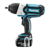
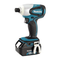
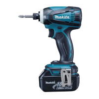
The Makita BTP141 (LXPT02*1) is a cordless 4-mode impact driver, an advanced version of the BTP140 model. It maintains the high versatility of its predecessor while featuring a more compact design. This is achieved through the integration of a Brushless DC (BLDC) motor and Makita's proprietary electronic clutch mechanism. The tool is powered by 18V Li-ion batteries, specifically the BL1815 (1.3Ah) and BL1830 (3.0Ah) models.
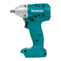
The BTP141 is available in several variations, including the BTP141Z and BTP141RFE. The BTP141Z does not include a battery fuel gauge, charger, battery, battery cover, or carrying case. In contrast, the BTP141RFE comes with a battery fuel gauge, a DC18RC charger, two BL1830 batteries, a battery cover, and a carrying case. All models include standard accessories as listed in the "Standard equipment" section of the manual.
Optional accessories are available to enhance the tool's functionality. These include various drill bits for wood, steel, and masonry, all with a 6.35mm Hex shank. Phillips bits and socket bits are also available. For charging, users can choose from several options: the Fast charger DC18RA (for U.S., Canada, Guam, Panama, Mexico, and Columbia), the Fast charger DC18RC (for all countries except those listed for DC18RA), the Charger DC18SD, the Charger DC24SC, and the Automotive charger DC18SE. Additional Li-ion batteries, BL1815 and BL1830, can also be purchased separately.
Maintenance of the BTP141 involves specific repair and lubrication procedures to ensure optimal performance and longevity. When repairing the machine, it is crucial to follow the instructions provided in the "Instruction manual" and adhere to all "Safety instructions."
For repairs, several specialized tools are necessary. The 1R003 Retaining ring pliers ST-2N and 1R212 Tip for retaining ring pliers are used for disassembling and assembling retaining ring WR-15. The 1R045 Gear extractor is used for disassembling and assembling the Hammer. A 1R223 Torque wrench shaft 20-90 N.m and 1R224 Ratchet head 12.7 are required for disassembling and assembling the Hammer case. The 1R282 Round bar for 8-50 is used for disassembling and assembling the Hammer. A 1R288 Screwdriver magnetizer assists in removing Steel ball 5.6. The 1R291 Retaining ring S and R pliers are used for mounting Retaining ring WR-15. An 1R351 Anvil holding Jig is used for disassembling and assembling the Anvil. The 1R390 Cam A assembling jig and 1R391 Hammer holding jig are used for assembling Cam A and disassembling/assembling the Hammer, respectively. Finally, a 134848-9 Socket 32-50 is used for disassembling and assembling the Hammer case.
Lubrication is a critical aspect of maintenance, and Makita grease N. No.2 should be applied to specific components to prevent unusual abrasion. Key areas for lubrication include the Cam A and Cam B (between the cams), the Steel ball 3 (whole portion), the Hammer change plate (tab portion), the Hammer change ring (inside the ring), the Pin guide (drum portion), Pin 1.2 - 3.5 (whole portion), Steel ball 3.5 (whole portion), Anvil (surface where Hammer contacts), Steel ball 5.6 (whole portion), and Pin 2.5 (whole portion). These components require a small amount of grease, with the Anvil specifically needing 2g.
Further lubrication points include Steel ball 3 (6 pcs), Steel ball 3 (34 pcs), Steel ball 3 (34 pcs) (whole portion), Spindle complete (spindle portion and pins for Gears 57, 58), Spur gear 41 (teeth portion), Spur gear 14B (teeth portion), Change lever (sliding area in Motor bracket), Internal gear 41 (groove portion where 4 pcs. of Pin 1.2 fit), Spur gear 14A complete (pins for Gears 63), and Spur gear 21 (teeth portion). These components also require a small amount of Makita grease N. No.2.
The impact assembly and anvil section require detailed disassembly and reassembly procedures. Disassembly begins by removing the Bit holder section and Bumper using 1R224. Next, the Hammer case assembly and Change ring are removed by attaching 1R224 to 1R223, setting Socket 32-50 to 1R224, and turning 1R223 counterclockwise. The Change ring and Leaf spring are then removed. The Impact assembly is separated, followed by the separation of Housing R from Housing L. The Impact assembly is then removed along with the Motor section, and the Speed change lever assembly and Switch unit are separated. Finally, the Impact assembly is separated from the Motor section.
Further disassembly of the Impact assembly involves shifting the Speed change lever assembly stick towards the Motor bracket side, turning the Motor bracket assembly counterclockwise, and pulling it off. The Impact assembly and Anvil section are then disassembled, including the Gear case assembly, Compression spring 5, Hammer section, Pin 1.2 (4 pcs.), Spur gear 14A, Steel ball 5.6, Steel ball 3 (6 pcs.), Spur gear 14B (5 pcs.), Internal gear 41, and Spur gear 21 (3 pcs.). The Hammer change plate, Hammer change ring, Compression spring 2 (2 pcs.), Sleeve 24, and Change case are then disassembled from the Gear case assembly. This involves removing the Pin guide and Pin 1.2-3.5, pulling up the Hammer change plate, pulling out the Hammer change plate downward, and removing the Hammer change ring, Compression spring 2, and Sleeve 24.
The Anvil disassembly involves removing Retaining ring WR-15, which may require using 1R003 and 1R212 if it's difficult to remove. If the retaining ring is stuck, Anvil wings are placed onto shallow notches of 1R351, and 1R390 is set to Retaining ring WR-15. Then, 1R390 is pressed with an Arbor press to return Cam A to its correct position, allowing the retaining ring to be removed with pliers. The Anvil itself is disassembled by setting the Gear case assembly to 1R351, pressing down the Anvil with an Arbor press, which causes the Anvil to drop into the deep notches of 1R351, separating the Anvil and Cam A from the Gear case assembly. Finally, Nylon washer 15 and O ring 12.5 are removed from the Anvil, and Cam B, 22 pcs. of Steel ball 3, and Cup washer are removed from the Gear case assembly by pushing them towards the Bit holder side.
Reassembly of the Anvil section involves several steps. First, 22 pcs of Steel ball 3 are placed into the Cup washer, and then the Cup washer and Cam B are assembled to the Gear case assembly. Next, O ring 12.5 and Nylon washer 15 are assembled to the Anvil, and the Anvil is placed on 1R351, fitting its wings to the shallow notch. The Gear case assembly is then set to the Anvil. Cam A is set to Cam B, facing its cam gear side. 1R390 is set on Cam A and pressed with an Arbor press until Cam A stops, ensuring the groove for Retaining ring WR-15 on the Anvil is reserved. While expanding Retaining ring WR-15 with 1R291, it is set to the tips of 1R003 with 1R212, and then mounted to the groove on the Anvil.
The Change case, Change sleeve, Pin guides with Pin 1.2-3.5, Compression spring 2, and Hammer change ring are assembled to the Gear case assembly. This involves locating the Change case's tail to the opposite side of the Notch for Speed change lever, inserting the Change sleeve into the Gear case assembly with its groove facing the motor side, aligning the elliptical hole of the Change case to that of the Gear case assembly, applying grease to the elliptical holes of the Change case, mounting the Pin guide with Pin 1.2-3.5, and mounting 2 pcs of Compression spring 2 and the Hammer change ring to the Gear case assembly. Finally, the Hammer change plates are assembled by pressing the Hammer change ring at two points.
The Hammer section is assembled to the Gear case assembly, and Spur gear 41 and Spur gear 14B are assembled. This includes assembling the Change ring to the Gear case assembly, assembling the Leaf spring and Sleeve 24 to the Gear case assembly, provisionally assembling the Hammer case assembly, placing Compression spring 5 and Steel ball 5.6 into the center hole of the Anvil, placing 6 pcs. of Steel ball 3 to the holes on the Outer hammer, inserting the Hammer section into the Gear case assembly, assembling Spur gear 41, and assembling five Spur gear 14B.
The Motor bracket section is then assembled. Ball bearing 607ZZ is mounted to the Motor bracket assembly, Spur gear 21 is mounted to Spur gear 14A, and Internal gear 41 is mounted to the Change lever, inserting 4 pcs of Pin 1.2. The assembled Spur gear 14A is mounted to the Motor bracket assembly, engaging the 3 pcs. of Spur gear 21 with Internal gear 50. The assembled Change lever is mounted to the Motor bracket assembly, aligning its three arms to the inner grooves.
Finally, the Motor bracket section is assembled to the Gear case assembly by fitting its three Protrusions to three depressions of the Gear case assembly and fitting the Change lever to the Notch in the wide depression of the Gear case assembly, then pushing and turning it clockwise.
The Speed change lever is assembled to the Impact assembly by inserting 2 pcs of Compression spring 3 and mounting the Speed change lever assembly. The Impact assembly is then fully assembled, and the Motor section is assembled to the Impact assembly. The 2 pcs of Switch unit are mounted to the Motor bracket assembly, and the Impact assembly together with the Motor section is set to Housing L. The F/R Change lever is assembled to the Switch, and the Switch plate complete is mounted to Housing L. The Hammer case assembly is tightened with Socket 32-50, 1R223, and 1R224, with a fastening torque of 15-20 N.m.
The Hammer section disassembly involves separating the Impact assembly with the Motor section, removing the Motor bracket assembly, disassembling the Hammer section from the Gear case assembly, and removing Steel balls and the Bearing case from the Hammer section. Steel ball 5.6, Compression spring 22, Steel ball 3 (34th), Flat washer 14, and Spindle complete are disassembled from the Outer hammer. This involves inserting 1R282 into the hole of the Spindle complete, mounting 1R391 to the Hammer, setting 1R045, turning the handle clockwise, and removing Steel ball 5.6.
Hammer section reassembly involves mounting 34 pcs. of Steel ball 3 to the Outer hammer and 6 pcs. of Pin 2.5 to the Hammer. Flat washer 14 is placed, and the Spindle complete is inserted. Compression spring 22 and the Hammer are mounted, 1R282 is set to the Spindle complete, and 1R391 to the Hammer. The Hammer is pulled down with 1R045, Steel ball 5.6 is mounted, and Ball bearing 6805LLB and the Bearing case are mounted to the Spindle complete, with 6 pcs. of Steel ball 3 mounted to the Outer hammer.
The Rotor disassembly involves separating Housing R from Housing L and disassembling the Motor section. The Motor section is placed on a workbench, and the Stator is pressed down to separate it from the Rotor. Reassembly involves inserting the Rotor into the Stator set on a workbench, controlling the strong magnet force, and slowly lifting the Stator set while controlling the magnet force to prevent it from sticking to the Fan side abruptly. When handling multiple rotors, it is important to keep them at an appropriate distance to avoid them sticking together, which could cause cracks or breaks.
The device's circuit diagram shows the wiring for the BTD141 18V model. It includes the Stator, Switch units for detecting work mode, Controller, and Terminal. The lead wires are color-coded (Black, Red, Blue, Yellow, Gray, White, Orange). The wiring diagram illustrates how the LED circuit's lead wires are fixed with the lead wire holder, ensuring they do not cross the ribs to prevent interference with Housing R. The Switch unit for detecting work mode is assembled by mounting the units with red lead wires to the Pin on the Housing R side and units with black lead wires to the Pin on the Housing L side. The final wiring in Housing L shows the routing of lead wires from the Stator, Switch units, and Controller, ensuring slack portions are managed and wires do not cross ribs.
| Type | Cordless Impact Driver |
|---|---|
| Voltage | 18V |
| Battery Type | Lithium-Ion |
| No Load Speed | 0-2, 600 rpm |
| Impact Rate | 0-3, 200 ipm |
| Weight | 1.5 kg |
| Chuck Size | 1/4" |