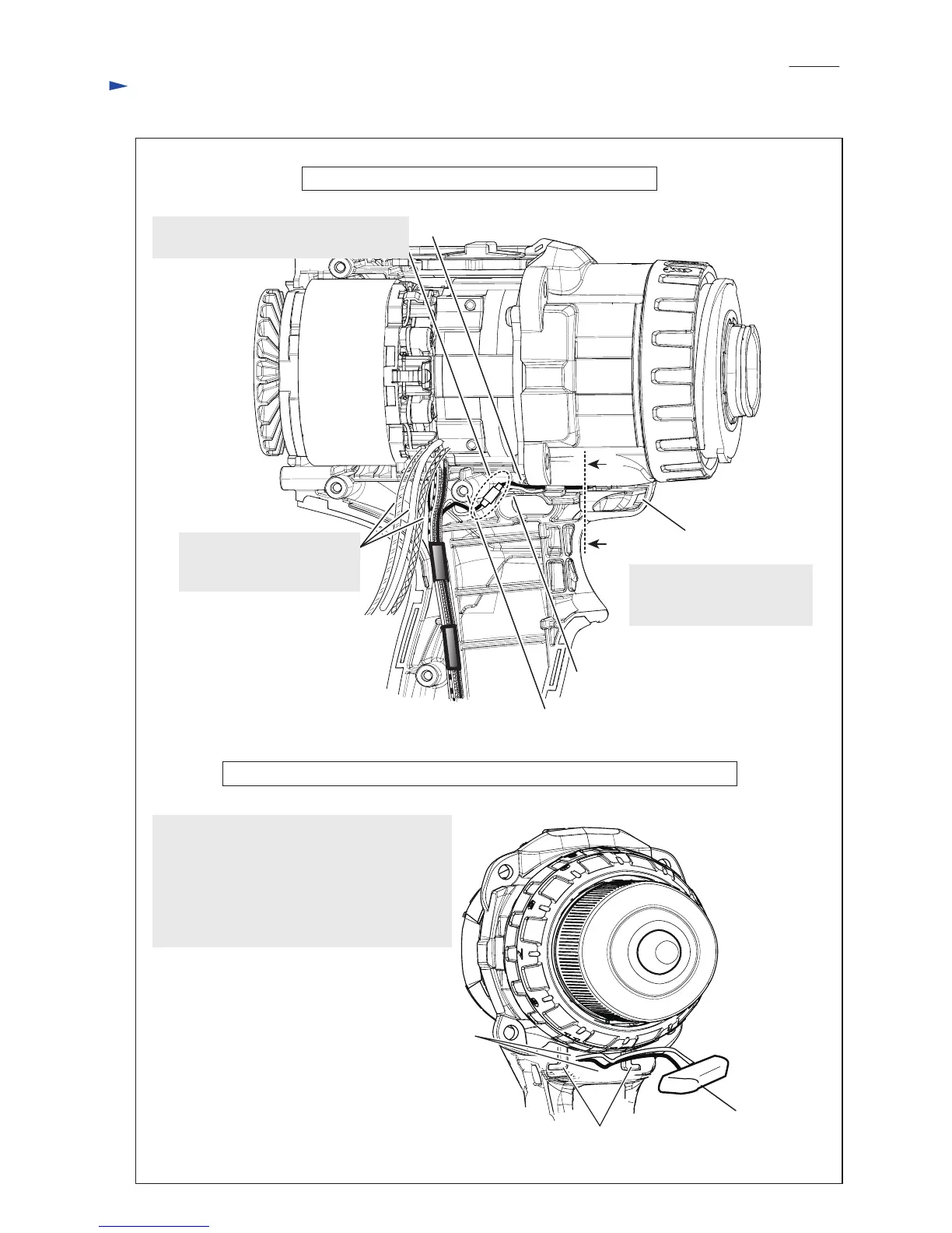
Wiring diagram
Fig. D-2
Rib A
Stator
Rib B
Boss
LED circuit
A’
A
See the following illustration
for the cross section
between A and A’.
LED circuit
(Insert it
as drawn above,)
View before setting Switch and F/ R change lever in place
Front view around the lead wires for LED circuit after setting Gear assembly in place
Note:
Be sure to route the lead wires for LED circuit
to the space between ribs of Gear assembly
after setting Gear assembly in place.
If the routing is done before assembling Gear
assembly, the breakage or pinching of the lead
wires will happen.
Ribs of Gear assembly
Lead wires for LED circuit
Place Connector this space among Rib A,
Rib B and Boss.
Thick lead wires from Stator
must be put on the other thin
lead wires.
P 8
/ 11
 Loading...