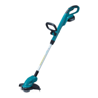
Red dot mark
Room for Ball bearing 608ZZ
of Gear shaft complete
Wire connecting
portions
Flag receptacles
While facing the wire connecting portions to Motor housing (L) side,
connect Lead wire (red) receptacle to the terminal with Red dot mark
and Lead wire (black) receptacle to the other terminal.
Motor housing
(L) side
Fig. D-2
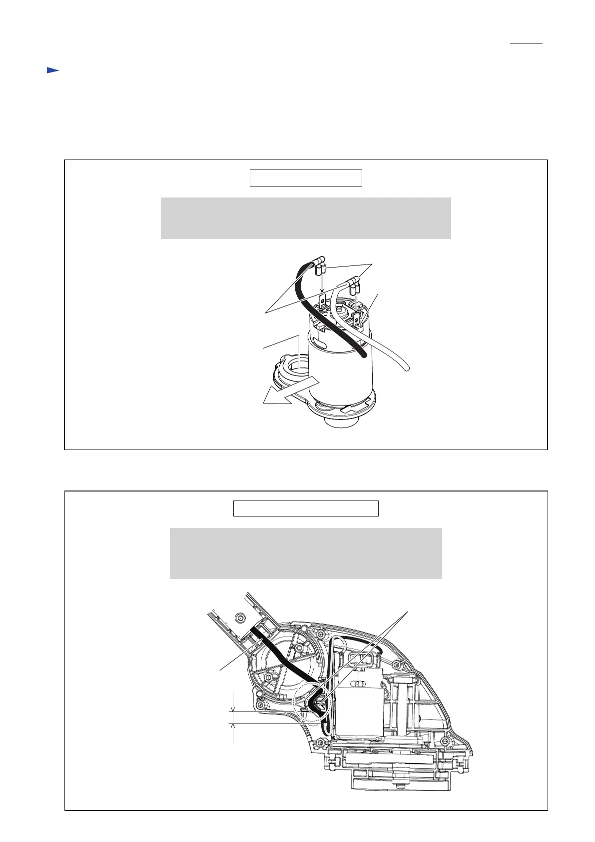
Fig. D-3
Wiring to DC motor
Wiring in Motor housing L
at least 5 mm
1. Come out at least 5 mm long portion of Power supply cord unit
from the lower edge of Labyrinth figured lead holders.
2. Make sure that Power supply cord unit is fixed in Labyrinth
figured lead holders.
Labyrinth figured
lead holders
Power supply cord unit
(black, white)
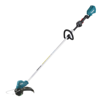
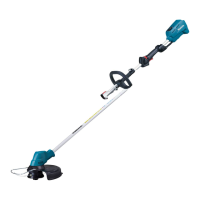
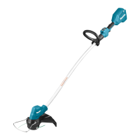
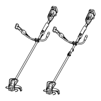
DUR141, DUR181
Wiring diagram
P 8/ 10
 Loading...