9
Use the optional keyless drill chuck assembly. When
installing it, refer to "Installing or removing the bit"
described on the previous page.
Set the change lever so that the pointer points to
the
symbol.
Hold the ring and turn the sleeve counterclockwise to
open the chuck jaws. Place the bit in the chuck as far as
it will go. Hold the ring firmly and turn the sleeve
clockwise to tighten the chuck. To remove the bit, hold
the ring and turn the sleeve counterclockwise.
CAUTION:
• Never use "rotation with hammering" when the
quick change drill chuck is installed on the tool.
The quick change drill chuck may be damaged.
• Pressing excessively on the tool will not speed up
the drilling. In fact, this excessive pressure will only
serve to damage the tip of your bit, decrease the
tool performance and shorten the service life of the
tool.
• There is a tremendous twisting force exerted on
the tool/bit at the time of hole breakthrough. Hold
the tool firmly and exert care when the bit begins to
break through the workpiece.
• Always secure small workpieces in a vise or similar
hold-down device.
Diamond core drilling
When performing diamond core drilling operations,
always set the change lever to the
position to use
"rotation only" action.
CAUTION:
• If performing diamond core drilling operations
using "rotation with hammering" action, the
diamond core bit may be damaged.
MAINTENANCE
CAUTION:
• Always be sure that the tool is switched off and
unplugged before attempting to perform inspection
or maintenance.
• Never use gasoline, benzine, thinner, alcohol or
the like. Discoloration, deformation or cracks may
result.
Lubrication
CAUTION:
• This servicing should be performed by Makita
Authorized or Factory Service Centers only.
This tool requires no hourly or daily lubrication because
it has a grease-packed lubrication system. However, it is
recommended to periodically replace the grease for
longer tool life.
Run the tool for several minutes to warm it up. Switch off
and unplug the tool.
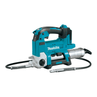
Loosen the four screws and remove the handle. Note
that the top screws are different from other screws.
1
1
008601
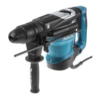
Disconnect the connector by pulling them.
1
008607
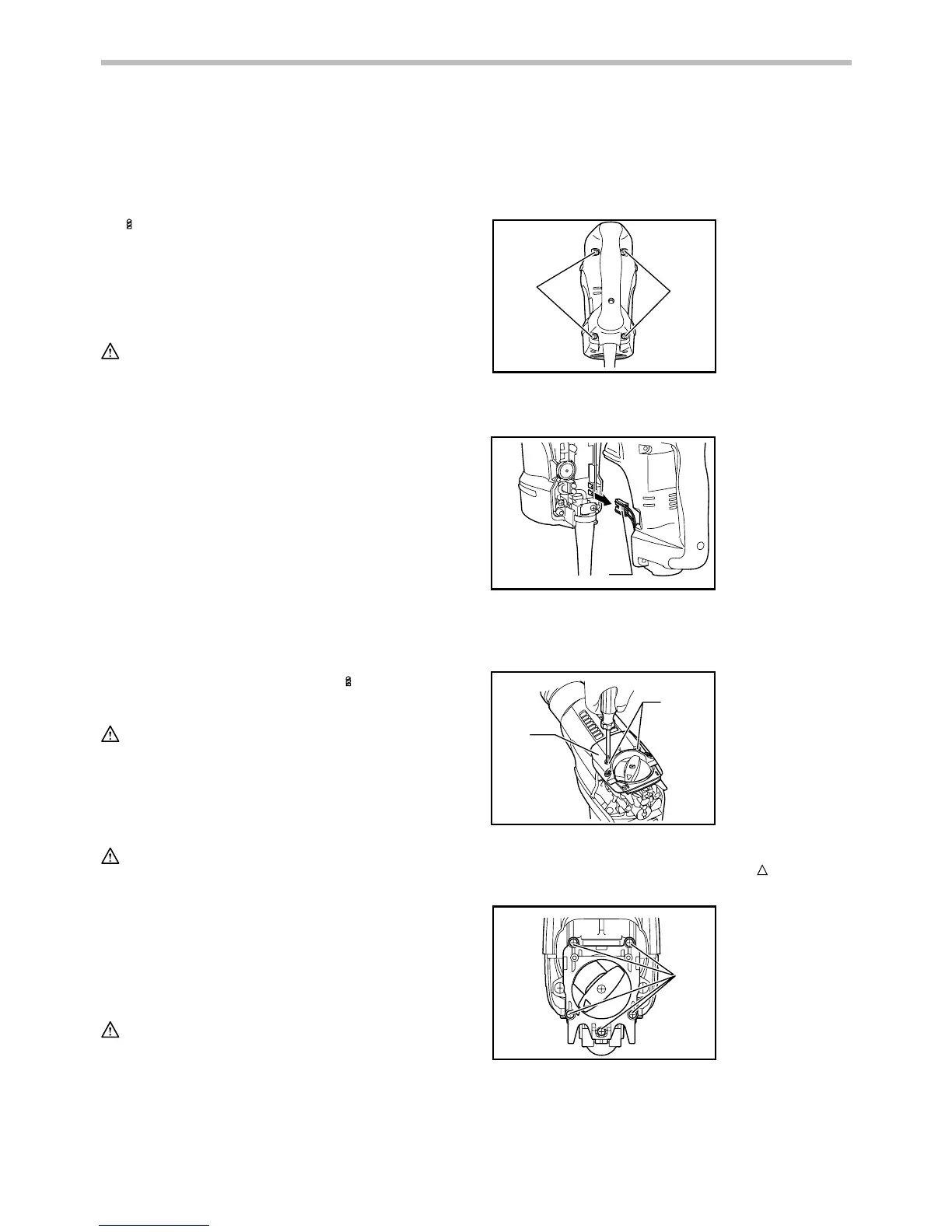
Loosen the two screws on crank cap cover and
remove the crank cap cover.
1
2
008602
Align the change lever with the symbol
, loosen the
five screws and then remove the crank cap.
1
008603
1. Screws
1. Crank cap cover
2. Screws
1. Connector
1. Screws
 Loading...