EasyManua.ls Logo

Makita LH1040F User Manual

Makita LH1040F
24 pages
To Next Page IconTo Next Page
To Previous Page IconTo Previous Page
Page #14 background imageLoading...
Page #14 background image
14
Vertical vise (optional accessory)
1
2
3
4
5
6
7
012655
The vertical vise can be installed in two positions on
either the left or right side of the guide fence or the holder
assembly (optional accessory). Insert the vise rod into
the hole in the guide fence or the holder assembly and
tighten the screw to secure the vise rod.
Position the vise arm according to the thickness and
shape of the workpiece and secure the vise arm by
tightening the screw. If the screw to secure the vise arm
contacts the guide fence, install the screw on the
opposite side of vise arm. Make sure that no part of the
tool contacts the vise when lowering the handle all the
way. If some part contacts the vise, re-position the vise.
Press the workpiece flat against the guide fence and the
turn base. Position the workpiece at the desired cutting
position and secure it firmly by tightening the vise knob.
CAUTION:
The workpiece must be secured firmly against the
turn base and guide fence.
Horizontal vise (optional accessory)
12
3
4
001807
The horizontal vise can be installed on either the left or
right side of the base. When performing 15° or greater
miter cuts, install the horizontal vise on the side opposite
the direction in which the turn base is to be turned. By
turning the vise knob counterclockwise, the screw is
released and the vise shaft can be moved rapidly in and
out. By turning the vise knob clockwise, the screw
remains secured. To grip the workpiece, turn the vise
knob gently clockwise until the projection reaches its
topmost position, then fasten securely. If the vise knob is
forced in or pulled out while being turned clockwise, the
projection may stop at an angle. In this case, turn the vise
knob back counterclockwise until the screw is released,
before turning again gently clockwise.
The maximum width of the workpiece which can be
secured by the horizontal vise is 130 mm.
Holders and holder assembly
(optional accessories)
1
2
012656
The holders and the holder assembly can be installed on
either side as a convenient means of supporting
workpieces horizontally. Install them as shown in the
figure. Then tighten the screws firmly to secure the
holders and the holder assembly.
When cutting long workpieces, use the holder-rod
assembly (optional accessory). It consists of two holder
assemblies and two rods 12.
2
1
002246
CAUTION:
Always support long workpieces level with the top
surface of the turn base for accurate cuts and to
prevent dangerous loss of control of the tool.
OPERATION
CAUTION:
Before use, be sure to release the handle from the
lowered position by pulling the stopper pin.
Make sure the blade is not contacting the
workpiece, etc. before the switch is turned on.
CUTTING AS MITER SAW
WARNING:
When using the tool in the miter saw mode, secure
the top table at the topmost position so that the saw
blade never protrudes from the top surface of the
top table.
1. Holder
assembly
2. Rod 12
1. Holder
assembly
2. Holder
1. Vise knob
2. Projection
3. Vise shaft
4. Base
1. Vise rod
2. Screw
3. Vise knob
4. Vise arm
5. Guide fence
6. Holder assembly
7. Holder
Question and Answer IconNeed help?

Do you have a question about the Makita LH1040F and is the answer not in the manual?

Makita LH1040F Specifications

General IconGeneral
Input power1650 W
Power sourceAC
Blade diameter160 mm
Idle speed (max)4800 RPM
Sound pressure level92 dB
Cutting capacity 45° miter35 x 130 mm
Cutting capacity 45° incline69 x 130 mm
Weight and Dimensions IconWeight and Dimensions
Depth530 mm
Width476 mm
Height535 mm
Weight14300 g

Summary

Specifications

General Power Tool Safety Warnings

Work Area Safety

Ensure a clean, well-lit workspace and keep bystanders clear to prevent accidents and injuries.

Electrical Safety

Follow electrical safety guidelines, including using proper outlets, avoiding wet conditions, and protecting cords.

Table Top Miter Saw Safety Warnings

Personal Safety

Prioritize personal safety with alertness, proper PPE, and correct tool handling to prevent injuries.

Power Tool Use and Care

Properly use and maintain the power tool, ensuring it's in good condition and used as intended to prevent damage.

Service

Ensure the power tool is serviced by qualified personnel using identical replacement parts for safety and reliability.

Installation

Installing Auxiliary Plate

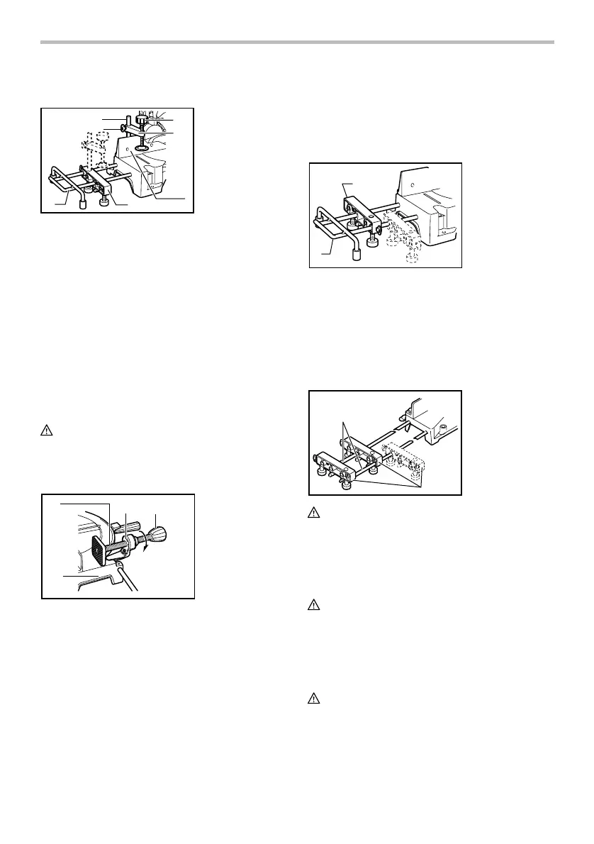
Secure the auxiliary plate to the tool's base using the provided notch and hex bolt before operation.

Functional Description

Installing Holders

Attach and adjust holders on the base sides, ensuring they contact the floor surface for stability.

Bench Mounting

Bolt the tool securely to a stable surface via the base holes to prevent tipping and ensure safe operation.

Blade Guard

Maintain blade guards in good condition and ensure their proper function; never remove or defeat them.

Adjusting Miter Angle

Maintaining Maximum Cutting Capacity

Ensure the tool is set up for maximum cutting capacity, checking blade position and adjusting if needed.

Adjusting Bevel Angle

Set the desired bevel angle by loosening the lever, tilting the blade, and tightening the lever securely.

Assembly

Switch Action

Verify the switch operates correctly before use; press ON to start and OFF to stop the tool.

Lighting Up Lamps

Operate the lamp switch for visibility on the LH1040F model, avoiding direct light exposure.

Adjusting Level of Top Table

Adjust the top table level by loosening levers, positioning the table, and re-tightening levers for correct mode operation.

Installing or Removing Saw Blade

Ensure the tool is unplugged before blade installation/removal, using the correct wrench and securing components properly.

Adjusting Riving Knife

Installing and Adjusting Rip Fence

Install and adjust the rip fence parallel to the blade to reduce kickback risk, aligning it with the workpiece edge.

Dust Bag

Securing Workpiece

Sub-Fence (for European countries only)

Position the sub-fence correctly for cuts; flip outward for left bevel cuts to avoid blade contact.

Operation

Vertical Vise (Optional Accessory)

Install and use the vertical vise for secure workpiece holding, positioning it on the guide fence or holder assembly.

Holders and Holder Assembly (Optional Accessories)

Install holders and holder assembly for horizontal workpiece support, especially for long pieces.

Horizontal Vise (Optional Accessory)

Install and use the horizontal vise for secure workpiece clamping, adjusting its position as needed.

Cutting as Miter Saw

When using miter saw mode, ensure the top table is at its highest position, preventing blade protrusion.

Cutting Aluminum Extrusion

Press Cutting

Secure workpiece, start tool, wait for full speed, gently lower handle, then stop and wait for blade to stop.

Miter Cutting

Perform miter cuts by following the 'Adjusting the Miter Angle' procedure for precise angle setting.

Bevel Cut

Execute bevel cuts by tilting the blade to the desired angle, ensuring safe operation and waiting for blade stop.

Compound Cutting

Combine miter and bevel angles for compound cuts, following specific procedures for accurate results.

Wood Facing

Cutting Repetitive Lengths

Use the set plate for efficient cutting of multiple pieces to the same length, ensuring accurate positioning.

Cutting as Table Saw (Bench Mode)

Operate in table saw mode with proper blade cover installation and safe practices like using push sticks.

Ripping

Work Helpers

Utilize work helpers like push sticks and blocks for safe cutting, preventing hand contact with the blade.

Push Block

Construct and use a push block from plywood for safe feeding of workpieces, with protective features.

Auxiliary Fence

Install and use an auxiliary fence for narrow rips, providing a safe guide when push sticks are not feasible.

Maintenance

Adjusting the Cutting Angle

Check and adjust miter and bevel angles for proper alignment and accurate cutting results.

Miter Angle

Fine-tune the miter angle alignment by adjusting the guide fence and blade position for square cuts.

Bevel Angle

Set and verify bevel angles accurately, ensuring the blade is correctly positioned at 0° or 45°.

Replacing Carbon Brushes

Regularly inspect and replace carbon brushes when worn down to the limit mark for optimal tool performance.

After Use

Perform post-operation cleaning, lubrication, and seek professional service for maintenance to ensure safety.

Optional Accessories

Related product manuals