P 2 / 8
Repair
[2] LUBRICATION
It is not required to lubricate the gear section because the portion is replaced as a factory-lubricated gear unit.
[3] DISASSEMBLY/ASSEMBLY
[3] -1. Drill Chuck
Fig. 2
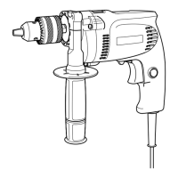
[1] NECESSARY REPAIRING TOOLS
CAUTION: Remove the battery cartridge from the machine for safety before repair/maintenance !
DISASSEMBLING
Description Use for
Hex wrench 10 Removing /mounting Drill chuck
Plastic hammer Removing Drill chuck
Hex wrench
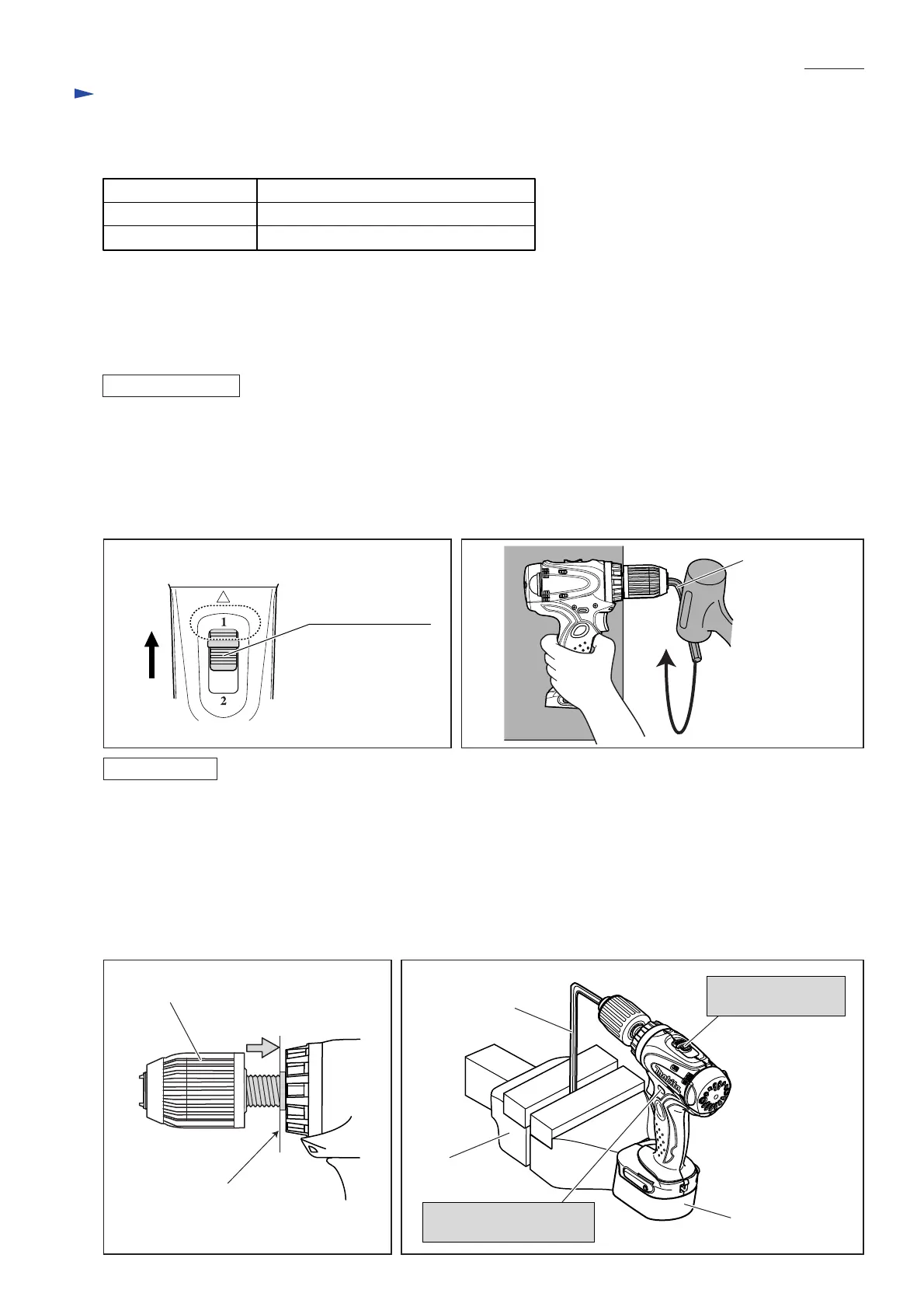
Fig. 1
Note: It is required to remove Drill chuck when replacing Gear assembly, but you need not when replacing only Housing.
1) Open the jaws of Drill chuck fully, and remove the chuck screw (Flat head screw M6x22, left-handed and threadlocker
coated) by turning clockwise with impact driver in Forward rotation mode.
2) Insert a hex wrench into Drill chuck. Then set the Speed change lever in Low speed as illustrated in Fig. 1.
Holding the machine on work bench firmly, turn Drill chuck counterclockwise by tapping the hex wrench. (Fig. 2)
Now Drill chuck can be removed from Spindle.
Fig. 3 Fig. 4
ASSEMBLING
1) Turn Drill chuck clockwise until it sits on the end of the threaded portion of Spindle. (Fig. 3)
2) See Fig. 4. Insert a hex wrench into drill chuck, and fix the other end of hex wrench in vise. Install battery.
Then set the Speed change lever in Low speed, and F/R change lever in Forward (clockwise) rotation mode.
3) Slowly pull the switch trigger to rotate Spindle until the motor is locked.
Note: Pull the trigger so that Spindle reaches full speed in one second.
Important: Be sure to release the switch trigger just after Spindle is locked.
4) Secure Drill chuck with the chuck screw by turning counterclockwise with impact driver.
Note: If you reuse the removed Flat head screw M6x22, apply threadlocker to threaded portion.
Battery
Hex wrench
Vise
End of the threaded
portion of Spindle
Drill chuck
Speed change lever:
in Low speed
F/R change lever:
in Forward rotation mode
Speed change lever
 Loading...