Installation and commissioning
MAN marine diesel engines D2868 LE4.. / D2862 LE4..
47
Carefully read through the Operating Instructions before starting any work!
This particularly applies to the General Safety Instructions section
and the safety instructions in the various chapters.
6.3.3 Checking the crankshaft axial clearance
NOTE
The designed crankshaft axial clearance of the engines must not in any event be reduced by the install
ation of couplings or other components.
Therefore:
S It is essential to determine the crankshaft axial clearance using a dial gauge held on a magnetic stand
before and after flange-mounting add-on parts.
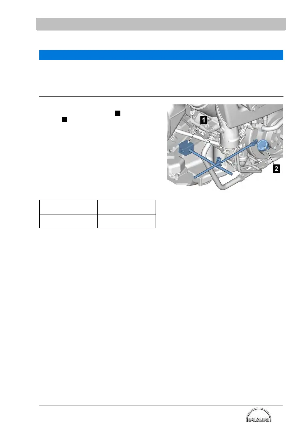
S Remove the V-belt guard
S Position the dial gauge holder
1
with dial
gauge
2
on the engine mounting so that the
dial gauge tracer pin is resting on the vibration
damper with a preload
S Press crankshaft all the way in the axial direc
tion to the flywheel housing
S Zero the dial gauge
S Pull crankshaft all the way in the axial direction
from the flywheel housing
S Check the dial gauge indicator
If the results of the two measurements to not
match or if the crankshaft springs back after being
moved, check the mounting.
Engines Crankshaft axial clear
ance
D2868 LE4..
D2862 LE4..
0.20-0.40 mm
 Loading...