Exhaust system
41
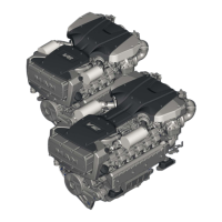
Exhaust gas outlet on the engine
On both the V8−1200 and V12−1800 both banks of
cylinders are routed to a central exhaust gas
outlet.
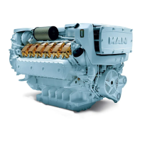
On both types, exhaust gas manifolds can be
provided either for an exhaust gas outlet to the
rear À or upwards Á.
The dimensions of the flange for the connection of
the boat−side exhaust gas system are shown on
the installation drawing.
Connecting exhaust system to engine
Install resilient connecting elements between
engine and exhaust system which permit engine
movement resulting from the resilient engine
mounting and isolate the engine vibrationally from
the exhaust system.
Either heat−resistant hoses (corrugated hoses
made of silicone) or bellow expansion joints can be
used for this purpose.
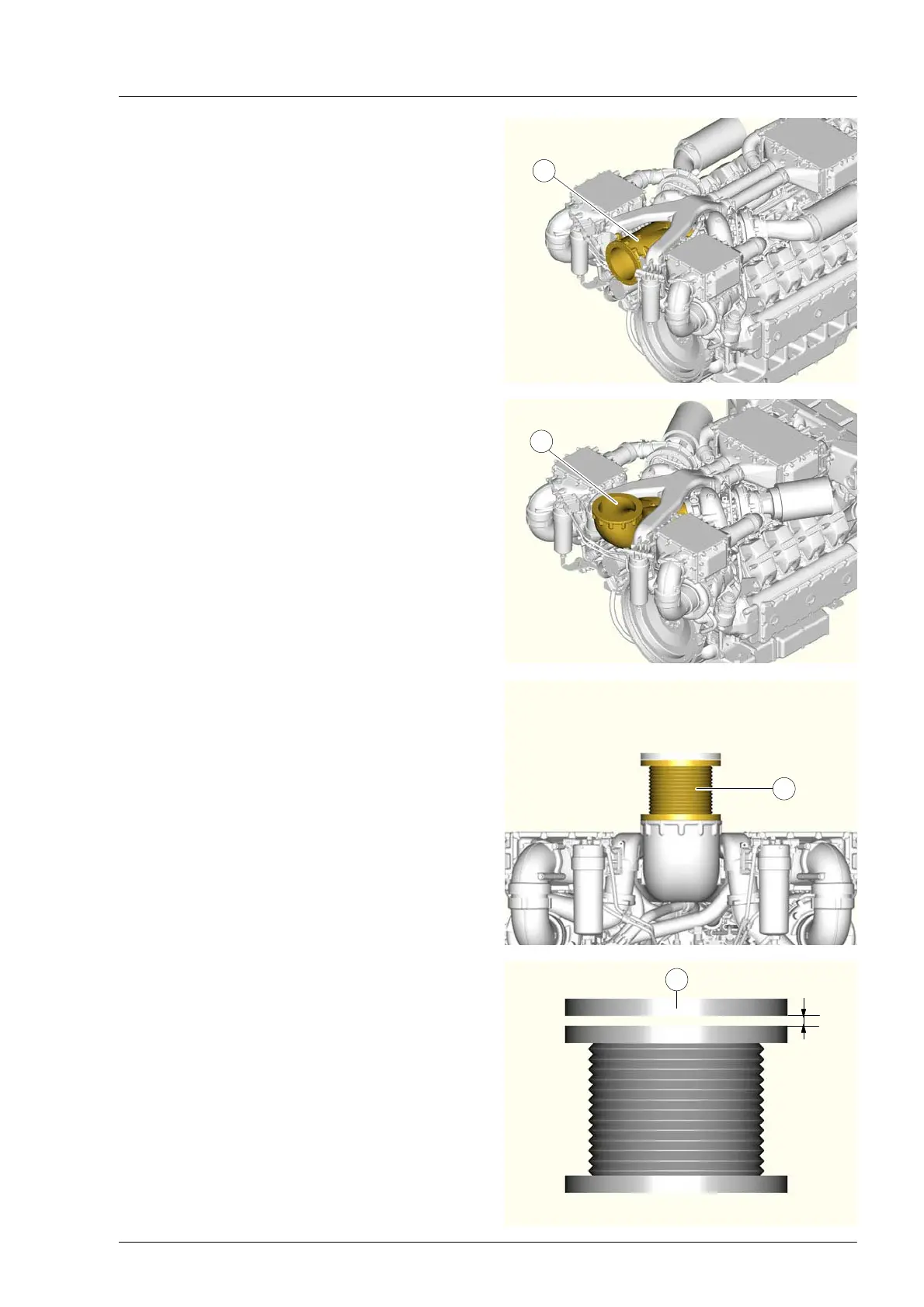
Installing exhaust bellow expansion joint
Exhaust pipe bellows  prevent the transfer of
vibration from the engine to the exhaust gas
system and compensate for expansion of the
exhaust pipe due to heating.
Installing the exhaust gas bellows under pre−-
tensile load.
Pre−tensile loading means that before screwing on
the bellows, the distance X between the flange of
the bellows and the mating flange of the
downstream exhaust pipe à should be 10−15mm.
For flange hole pattern and dimensions see
installation drawing.
1
2
3
x
4
 Loading...