EasyManua.ls Logo

Manitowoc QD1302A User Manual

Manitowoc QD1302A
175 pages
To Next Page IconTo Next Page
To Previous Page IconTo Previous Page
Page #81 background image
Section 6 Electrical System
Part No. 80-1100-3 6-25
Q1300/Q1800 - SELF CONTAINED - 1 PHASE WITH TERMINAL BOARD
R
R
C
S
R
TB31
TB37
TB32
TB35
L1
TB34
*OVERLOAD
(53)
TB33
(52)
(51)
(48)
(45)
(46) (50)
(49)
(47)
(55)
(61)
(77)
(76)
(60)
(98)
(57)
(74)
(58)
(59)
(73)
(99)
(85) (86)
1F
1C
4
1
3
5
FUSE (7A)
TRANS.
(56)
ICE THICKNESS PROBE
(75)
LH HARVEST
SOLENOID
DUMP
SOLENOID
(81)
(80)
WATER
PUMP
TB3
0
TB3
0
TB3
0
TB3
0
CONTACTOR
COIL
HIGH PRES
CUTOUT
BIN SWITCH LIGHT
HARVEST LIGHT/
SAFETY LIMIT CODE LIGHT
LOW D.C.
VOLTAGE
PLUG
TB35
TB3
0
CRANKCASE HEATER
(94)
(95)
T
B35
TB3
0
CONTACTOR
CONTACTS
CONTACTOR
CONTACTS
L2
L1
(96)
(42)
COMPRESSOR
RUN CAPACITOR
FAN CYCLE CONTROL
FAN MOTOR
(AIR COOLED ONLY)
RUN CAPACITOR**
L2(N)
SEE SERIAL PLATE FOR VOLTAGE
CAUTION: DISCONNECT POWER BEFORE WORKING
ON ELECTRICAL CIRCUITRY.
DIAGRAM SHOWN DURING FREEZE CYCLE
TERMINATES AT
PIN CONNECTION
PTCR
(44)
(64)
(63)
BIN SWITCH
(62)
(66)
(65)
(69)
(67)
(68)
TOGGLE SWITCH
68
67
69
66
62
ICE
OFF
CLEAN
(66)
(62)
VIEW FOR WIRING
INTERNAL WORKING
VIEW
WATER
VALVE
(21)
(22)
CLEAN LIGHT
WATER LEVEL LIGHT
WATER LEVEL PROBE
2
(87)
(88)
RH HARVEST
SOLENOID
1G
AUCS DISPENSE TIME
(20)
SV1652

Table of Contents

Other manuals for Manitowoc QD1302A

Question and Answer IconNeed help?

Do you have a question about the Manitowoc QD1302A and is the answer not in the manual?

Manitowoc QD1302A Specifications

General IconGeneral
Ice TypeHalf Dice
Weight285 lbs
CondenserAir-Cooled
Production Capacity1300 lb/24 hours
Power Supply208-230/60/1
RefrigerantR404A
Ice Production130 lbs per day

Summary

Safety Notices

PERSONAL INJURY POTENTIAL

Warning about operating misused, abused, neglected, or altered equipment.

Warning

Alerts to potential personal injury situations.

Procedural Notices

Important

Provides useful information for performing procedures efficiently.

Section 1 General Information

Model Numbers

Explains the structure of model numbers.

Section 1 General Information

Warranty Coverage

Details the warranty terms and conditions.

Section 2 Installation Instructions

Ice Machine Dimensions

Provides physical dimensions of ice machines.

Section 2 Installation Instructions

Ice Storage Bin Dimensions

Provides dimensions for ice storage bins.

Section 2 Installation Instructions

Remote Condenser Dimensions

Provides dimensions for remote condensers.

Section 2 Installation Instructions

Location of Ice Machine

Critical for proper operation and maintenance.

Section 2 Installation Instructions

Leveling the Ice Storage Bin

Ensures proper functionality and door seal.

Section 2 Installation Instructions

Electrical Service

Critical for safe and proper operation.

Section 2 Installation Instructions

Self-Contained Electrical Wiring Connections

Essential for proper electrical hookup.

Section 2 Installation Instructions

Remote Electrical Wiring Connections

Essential for proper electrical hookup of remote units.

Section 2 Installation Instructions

Water Supply and Drain Requirements

Crucial for ice machine function and longevity.

Section 2 Installation Instructions

Remote Condenser/Line Set Installation

Key installation steps for remote setups.

Section 2 Installation Instructions

CALCULATING REMOTE CONDENSER INSTALLATION DISTANCES

Procedure for determining optimal placement.

Section 2 Installation Instructions

REMOTE RECEIVER SERVICE VALVE

Instructions for operating the service valve.

Section 2 Installation Instructions

Section 2 Installation Instructions

Installation Check List

Comprehensive checklist for installation verification.

Section 3 Maintenance

Component Identification

Identifies key parts of the ice machine.

Section 3 Maintenance

Operational Checks

Routine checks for proper operation.

Section 3 Maintenance

Cleaning the Condenser

Essential for maintaining performance.

Section 3 Maintenance

Interior Cleaning and Sanitizing

Crucial for hygiene and performance.

Section 3 Maintenance

CLEANING PROCEDURE

Step-by-step cleaning instructions.

Section 3 Maintenance

SANITIZING PROCEDURE

Step-by-step sanitizing instructions.

Section 3 Maintenance

AUTOMATIC CLEANING SYSTEM (AuCS)

Details on the automated cleaning accessory.

Section 3 Maintenance

Ice Thickness Probe

Maintenance and cleaning of the probe.

Section 3 Maintenance

Water Inlet Valve

Maintenance and cleaning of the water inlet valve.

Section 3 Maintenance

FILTER REPLACEMENT PROCEDURE

Steps for replacing filter cartridges.

Section 3 Maintenance

Removal from Service/Winterization

Procedures for preparing the machine for storage.

Section 4 Ice Machine Sequence of Operation

Self-Contained Air- and Water-Cooled

Describes the operational sequence for these models.

Ice Machine Sequence of Operation

HARVEST SEQUENCE

Details the harvest cycle.

Ice Machine Sequence of Operation

Remote

Describes the operational sequence for remote models.

Section 5 Water System Ice Making Sequence of Operation

Section 6 Electrical System

Energized Parts Charts

Lists parts energized during different operational states.

Section 6 Electrical System

Wiring Diagram Sequence of Operation

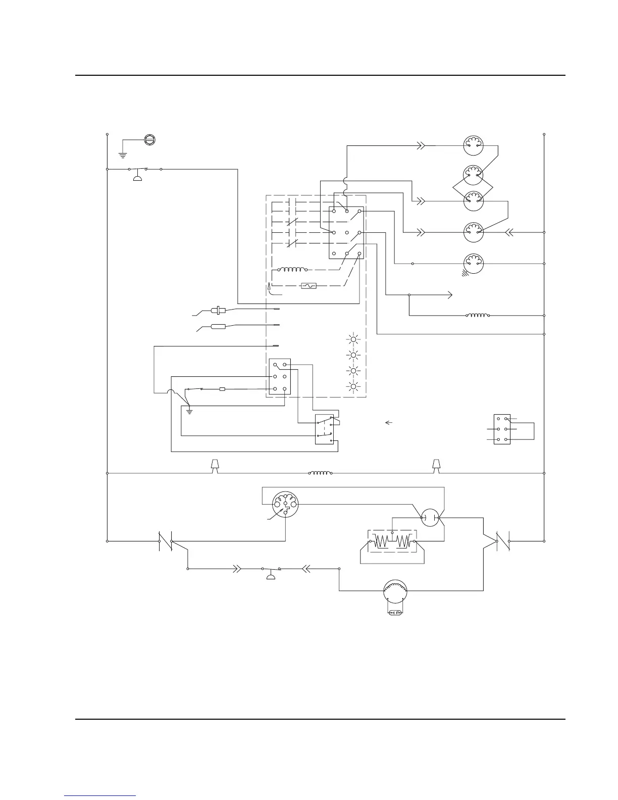
Explains the wiring diagrams.

Section 6 Electrical System

REFRIGERATION SYSTEM START-UP

Details the initial electrical startup sequence.

Section 6 Electrical System

Freeze Sequence

Electrical aspects of the freeze sequence.

Section 6 Electrical System

Harvest Sequence

Electrical aspects of the harvest sequence.

Section 6 Electrical System

AUTOMATIC SHUT-OFF

Electrical sequence for automatic shut-off.

Section 6 Electrical System

REMOTE MODELS

Electrical specifics for remote models.

Section 6 Electrical System

FREEZE

Electrical sequence during freeze for remote models.

Section 6 Electrical System

HARVEST

Electrical sequence during harvest for remote models.

Section 6 Electrical System

AUTOMATIC SHUT-OFF

Electrical sequence for automatic shut-off for remote models.

Section 6 Electrical System

Wiring Diagrams

Provides various wiring diagrams.

Section 6 Electrical System

Section 6 Electrical System

Section 6 Electrical System

Section 6 Electrical System

Section 6 Electrical System

Section 6 Electrical System

Section 6 Electrical System

Q800/Q1000 -REMOTE - 3 PHASE WITH TERMINAL BOARD

Wiring diagram for specific models.

Section 6 Electrical System

Q1300/Q1800 - REMOTE - 1 PHASE WITH TERMINAL BOARD

Wiring diagram for specific models.

Section 6 Electrical System

Q1300/Q1800 - REMOTE - 3 PHASE WITH TERMINAL BOARD

Wiring diagram for specific models.

Section 6 Electrical System

Component Specifications and Diagnostics

Component specs and diagnostic procedures.

Section 6 Electrical System

COMPRESSOR ELECTRICAL DIAGNOSTICS

Troubleshooting compressor electrical issues.

Section 6 Electrical System

PTCR DIAGNOSTICS

Explains PTCR function and diagnostics.

Section 6 Electrical System

Troubleshooting PTCR’s

Common PTCR failure modes and troubleshooting.

Section 6 Electrical System

CHECKING THE PTCR

Step-by-step guide to checking the PTCR.

Section 6 Electrical System

ICE/OFF/CLEAN TOGGLE SWITCH

Function and testing of the toggle switch.

Section 6 Electrical System

ELECTRONIC CONTROL BOARD

Overview of the control board components.

Section 6 Electrical System

Safety Limits

Built-in safety features of the control board.

Section 6 Electrical System

Ice Thickness Probe (Harvest Initiation)

How the probe works and initiates harvest.

Section 6 Electrical System

DIAGNOSING ICE THICKNESS CONTROL CIRCUITRY

Troubleshooting the ice thickness circuit.

Section 6 Electrical System

Section 6 Electrical System

Water Level Control Circuitry

How the water level is controlled.

Section 6 Electrical System

DIAGNOSING FREEZE CYCLE POTABLE WATER LEVEL CONTROL CIRCUITRY

Troubleshooting water level control issues.

Section 6 Electrical System

Section 6 Electrical System

Diagnosing An Ice Machine That Will Not Run

Troubleshooting general startup issues.

Section 7 Refrigeration System

Sequence of Operation

Explains how the refrigeration system works.

Refrigeration System

Harvest Cycle Refrigeration Sequence

Details the harvest cycle refrigeration.

Section 7 Refrigeration System

REMOTE MODELS

Refrigeration sequence for remote models.

Section 7 Refrigeration System

Automatic Shut-Off

Automatic shut-off in the refrigeration system.

Section 7 Refrigeration System

Q1300/Q1600/Q1800 REFRIGERATION TUBING SCHEMATICS

Diagrams of the refrigeration tubing.

Section 7 Refrigeration System

Operational Analysis (Diagnostics)

Key section for troubleshooting.

Section 7 Refrigeration System

ICE PRODUCTION CHECK

How to check ice production.

Section 7 Refrigeration System

INSTALLATION/VISUAL INSPECTION CHECKLIST

Checklist for installation verification.

Section 7 Refrigeration System

ICE FORMATION PATTERN

Analyzing ice formation for diagnostics.

Section 7 Refrigeration System

SAFETY LIMITS

Explains safety limits and their indications.

Section 7 Refrigeration System

Safety Limit #1

Details on safety limit 1.

Section 7 Refrigeration System

Section 7 Refrigeration System

Section 7 Refrigeration System

Section 7 Refrigeration System

HARVEST VALVE TEMPERATURE CHECK

Diagnostic procedure.

Section 7 Refrigeration System

Section 7 Refrigeration System

Section 7 Refrigeration System

Section 7 Refrigeration System

HARVEST PRESSURE REGULATING (H.P.R.) SYSTEM

Explanation of the HPR system.

Section 7 Refrigeration System

HPR DIAGNOSTICS

Troubleshooting the HPR system.

Section 7 Refrigeration System

HEADMASTER CONTROL VALVE

Operation and diagnostics of the headmaster valve.

Section 7 Refrigeration System

LOW ON CHARGE VERIFICATION

Procedure to check for low refrigerant charge.

Section 7 Refrigeration System

Pressure Control Specifications and Diagnostics

Specs and diagnostics for pressure controls.

Section 7 Refrigeration System

Section 7 Refrigeration System

Refrigerant Recovery/Evacuation and Recharging

Essential procedure for handling refrigerant.

Section 7 Refrigeration System

Self-Contained Charging Procedures

Steps for charging refrigerant.

Section 7 Refrigeration System

NORMAL REMOTE MODEL PROCEDURES

Specifics for remote units.

Section 7 Refrigeration System

Remote Charging Procedures

Steps for charging refrigerant in remote units.

Section 7 Refrigeration System

SYSTEM CONTAMINATION CLEAN-UP

Procedures for cleaning contaminated systems.

Section 7 Refrigeration System

Mild System Contamination Cleanup Procedure

Steps for mild contamination.

Section 7 Refrigeration System

REPLACING PRESSURE CONTROLS WITHOUT REMOVING REFRIGERANT CHARGE

Procedure to replace controls without discharging refrigerant.

Section 7 Refrigeration System

FILTER-DRIERS

Information about filter-driers.

Section 7 Refrigeration System

REFRIGERANT DEFINITIONS

Definitions related to refrigerant handling.

Section 7 Refrigeration System

REFRIGERANT RE-USE POLICY

Guidelines for refrigerant reuse.

Section 7 Refrigeration System

HFC REFRIGERANT QUESTIONS AND ANSWERS

Important information about HFC refrigerants.

Related product manuals