Introduction
The relationship between the guitarist and amplifier has been our prime concern since the earliest
Marshall’s were produced. We always aim to give that extra edge, which can help to inspire the player,
fuelling creativity and the ability to express.
Advances in technology have allowed us to modify and enhance this basic principle for the benefit of the
musician. However, we have never lost sight of that extra emotional drive that only valves are capable of
producing. The whole character of our unique sound emanates from the breathing full bodied pure tone of
the valve.
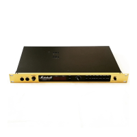
Your JMP-1 MIDI pre-amp is a carefully designed coalescence between modern MIDI technology and
classic Marshall valve circuitry. It’s many tones are all valve generated and presented in a way that is both
comfortable and familiar to guitar players.
The digital control capabilities add a new degree of flexibility to the way in which the tones can be switched
and processed. The advantages provided by this level of control are truly astounding. After studying the
manual and with a little practical exploration, you will find an unbelievable range of sounds and will very soon
wonder how you managed without MIDI. The only limit is your own imagination.
JMP-1 Front Panel Features
1. Input Socket Connect the guitar to this socket.
2. Headphone Socket For the connection of stereo headphones.
Headphones with an impedance of 600 Ohms will give
the best performance. Connecting headphones does not
disable the outputs of the pre-amp.
3. Output Level Control Controls the volume level from the master left and right
outputs (Item 25).
4. Display The display is split into two sections and shows patch
and data information.
5. Patch Key Push this key to enter patch selection mode (0-99). The
patch key LED will illuminate to indicate patch mode.
6. Store Key Use this key to store a patch in the memory.
Operational Note:
Push once and the store key LED will flash. The data entry control (7) can now be used to change the storage location.
Pushing patch or a parameter key will abandon the store. Push the store key again to complete the store. (Also see
section Creating Your Sounds).
7. Data Entry Control This rotary control is used to increment/decrement data
information, or to select a patch in patch mode.
8. Volume Key Push this key to adjust the patch volume level between 0
and 20. The volume key LED will illuminate to indicate
that the volume parameter has been selected. The data
display will show the current value. The value can then
be adjusted using the rotary data entry control (7).
9. Gain Key Push this key to adjust the level of gain between 0 - 20.
2
 Loading...

