56 57
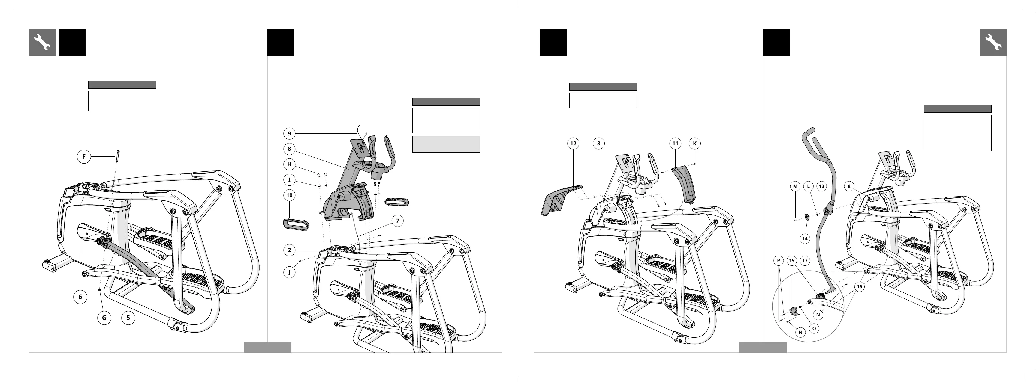
A Open HARDWARE FOR STEP 4.
B Attach the REAR TOP CAP COVER (11) to the
UPPER ASSEMBLY (8) using 2 SCREWS (K).
C Attach the FRONT TOP CAP COVER (12) to the
UPPER ASSEMBLY (8) using 2 SCREWS (K).
4 5
Hardware For Step 4
Description Qty
K Screw 4
Hardware For Step 5
Description Qty
L
M
N
O
P
Flat Washer
Bolt (20 mm)
Screw (8 mm)
Bolt (25 mm)
Screw (12 mm)
2
2
4
2
4
A Open HARDWARE FOR STEP 5.
B Slide the UPPER DUAL ACTION ARM (13) onto the UPPER ASSEMBLY
(8) and attach using 1 FLAT WASHER (L) , 1 HANDLEBAR CAP
(14) and 1 BOLT (M). Torque settings: 64.5 Nm / 47.6 lb-ft.
C Attach inside LINK ARM COVER (15) to LINK ARM (16) using 1 SCREW (N).
D Slide LINK ARM (16) onto the lower DUAL ACTION ARM (17) and
attach using 1 BOLT (O) and tighten to 80 Nm / 59 lb-ft.
E Attach outside LINK ARM COVER (15) to LINK ARM
(17) using 2 SCREWS (P) and 1 SCREW (N).
F Repeat steps B–E on other side.
G Move frame off Styrofoam base and cardboard.
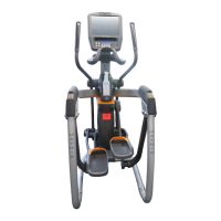
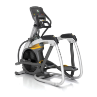
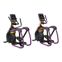
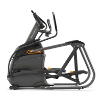
A50 SHOWN
ENGLISH
A Open HARDWARE FOR STEP 2.
B Slide LEFT PEDAL ARM (5) onto CRANK (6) and attach using
1 BOLT (F) and 1 NUT (G) and tighten to 77.4 Nm / 57 lb-ft.
2 3
Hardware For Step 2
Description Qty
F
G
Bolt
Nut
1
1
A Open HARDWARE FOR STEP 3.
B Carefully pull the CABLE (7) through the UPPER ASSEMBLY (8)
using the LEAD WIRE (9) located inside the UPPER ASSEMBLY (8).
C Attach UPPER ASSEMBLY (8) to MAIN FRAME (2) using 4 BOLTS
(H) and 4 FLAT WASHERS (I) and tighten to 64.5 Nm / 47.6 lb-ft.
D Insert 2 SCREWS (J) into bottom rear of MAIN FRAME (2).
E Insert INCLINE FRAME BOOTS (10) into
bottom area of UPPER ASSEMBLY (8).
Hardware For Step 3
Description Qty
H
I
J
Bolt
Flat Washer
Screw
4
4
2
Note: Be careful not to pinch
any wires while attaching the
upper assembly.
A50 SHOWN
ENGLISH
MXR20_AG_A30_A50_r1_1_B.indd 56-57MXR20_AG_A30_A50_r1_1_B.indd 56-57 12/3/20 2:41 PM12/3/20 2:41 PM
 Loading...