48
Technical Description, con’t
Figure 103
Figure 104
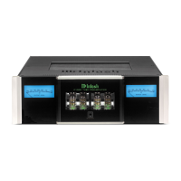
meter were
capable of
such high ve-
locity move-
ment, the hu-
man eye could
not perceive
the displayed
information.
McIntosh
solved both
problems elec-
trically. By
developing
electronic cir-
cuits the
meters are
made to respond to short intervals with an accuracy of
95%! To permit the eye to see such high speed motion, the
electronic circuits that drive the meter pointer are time
stretched. Special logarithmic circuitry allows the meter to
indicate a 60dB plus range, without resorting to a Meter
Range Switch.
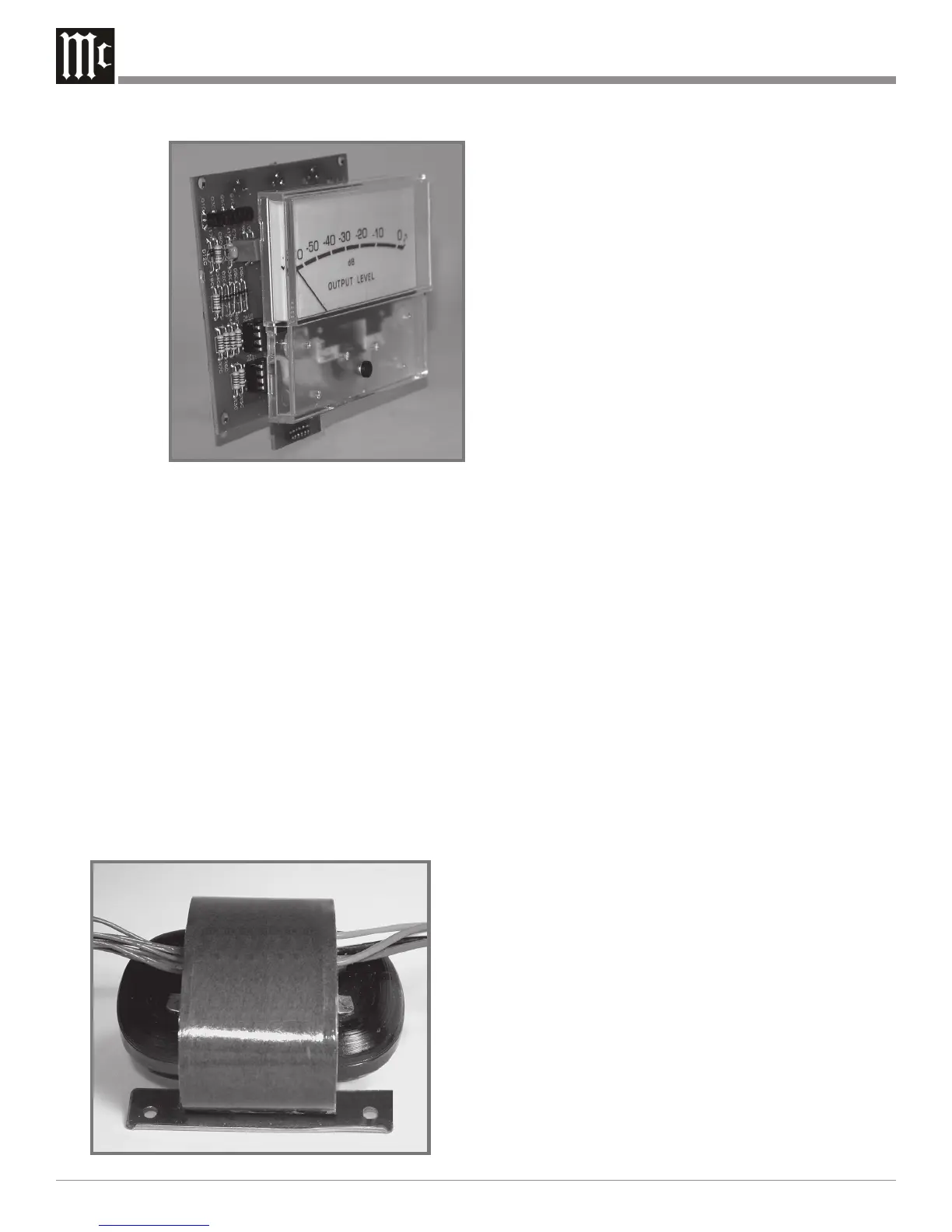
Power Supply Circuits
To compliment the design of the C1000, there are two
indentical fully regulated power supplies, one for each chan-
nel. The Power Supply is designed to allow both the
C1000P and C1000T Preamplifiers to be connected to the
C1000C simultaneously. The C1000 Contoller contains the
low and high voltage regulated power supplies for each
channel. The special “R” core transformers, one for each
channel, supply the necessary voltage/current for the low
and high voltage regulated circuitry and are housed in
shielded enclosures. Refer to figure 104.
Most owners desire one power switch for the whole au-
dio system. The C1000 Controller is equipped with circuits
providing remote Power Control On/Off signals to McIn-
tosh Source Components and Power Amplifiers. When the
C1000C is switched On, a digital “1” (+5V) signal changes
the operational state of digital control circuitry and a DC
voltage is sent to the Power Control Main Jacks. There are
also special Power Control Jacks (Triggers and Passthru)
and together with options in SETUP allow for the customiz-
ing of the Power Control Control Signals In for specific
functions.
Block Diagrams
Refer to folded sheet “Mc6A” for the C1000 Preamplifier
and C1000 Controller Block Diagrams. The Block Diagram
of the C1000 Tube Preamplifier is on folded sheet “Mc6B”.
 Loading...