5
Installation
Painting the Loudspeaker
The CS100 Ceiling Loudspeaker System is primed and
may be painted before or after installation.
The Loudspeaker Frame:
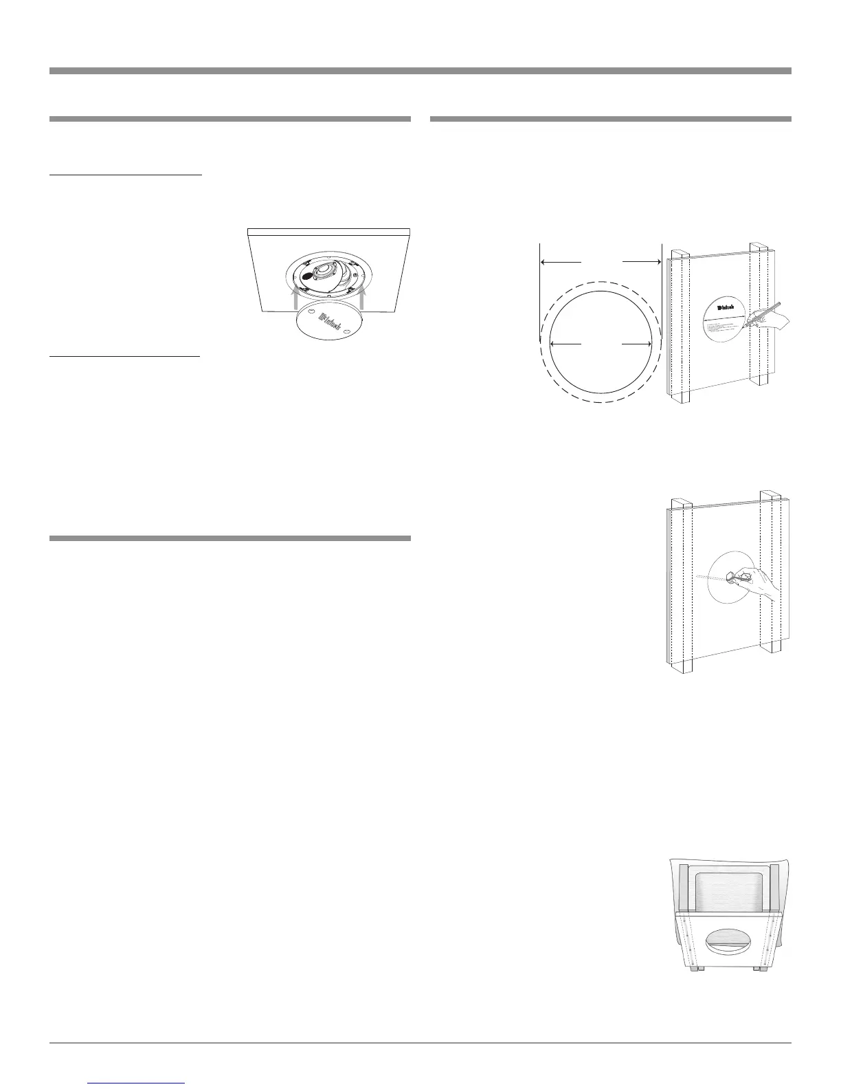
1. Insert the supplied paint shield into the frame of the
Loudspeaker. Refer to figure 5.
2. Paint the frame with light
coats, to help prevent ex-
cessive paint buildup and
“runs” on the frame.
3. After the paint has dried,
use the finger pulls to re-
move the paint shield.
The Loudspeaker Grille:
1. Carefully remove the cloth
from the inside of the grille. Set it aside in a clean loca-
tion.
2. Paint the grille with very light coats, to help prevent
paint from filling the holes in the grille.
3. After the paint is dry, reinstall the previously removed
grille cloth.
Figure 5
Installing the Loudspeaker
Follow the instructions below for installation using appro-
priate tools. If the optional RK100 Rough-In Kit Bracket
has been previously installed, go directly to step 6:
1. Place the supplied Hole Cutting Template to the desired
mounting location in the ceiling and trace the outside
edge of the template onto the mounting surface. Refer
to figures 5
and 6.
2. In the center
of the circle
just drawn on
the mount-
ing surface,
make a
small pilot
hole. Insert
a long wire
(with an insulated handle) into
the opening and verify there are no objects located in
the ceiling where the Loudspeaker will be installed.
Refer to figure 7.
Note: Check to make sure the thick-
ness of the ceiling material
is at least 3/8 inch (0.95cm),
as this is necessary for the
Loudspeaker’s clamping
devices to provide a secure
mounting.
3. Cut out and remove the piece of
ceiling material.
4. Install the Loudspeaker hookup
cable from the location of the Au-
dio Component(s) (Power Ampli-
fier) to the opening. Using a suitable securing device,
attach the cable inside the ceiling making sure to leave
about 24 inches (60.96cm) of cable.
Note: This will make for easier connection of the cable to
the Loudspeaker and allow for rotation of the Loud-
speaker after installation.
5. Install into the ceiling opening nonflammable sound
absorbing material (such as fiberglass) to reduce sound
leakage into other areas and
reduce acoustical standing waves/
resonances. If there already is pa-
per or aluminum backed fiberglass
located in the ceiling, remove the
backing where it would come into
contact with the rear of the Loud-
speaker. Refer to figure 8.
Preparing for Installation
In determining the CS100 Loudspeaker location, it is
important to keep away from any heating/cooling duct-
work, electrical wiring and plumbing that may be located
in the ceiling between the joists. The CS100 is designed for
indoor use only. Indoor rooms with high humidity levels
should be avoided; i.e. an indoor swimming pool area,
directly above a bathtub/shower/jacuzzi/sauna, etc.
When mounting the CS100 Ceiling Loudspeaker Sys-
tem to a building structure, it is important to follow all of
the local building/construction codes. Make sure the ceil-
ing structural members can support a weight of five times
the total weight of the Ceiling Loudspeaker System.
When the CS100 will be installed into a room under
constuction, it is advisable to install the optional McIntosh
RK100 Rough-In Kit Bracket into the joists. The bracket
provides a rigid mounting location for the Loudspeaker,
a secure tie off point for the hookup cable and allows for
easier finishing of the ceiling surface.
If the RK100 Rough-In Kit Bracket is used, install the
Loudspeaker hookup cable from the location of the Audio
Component(s) (Power Amplifier) to the bracket making
sure to leave about 24 inches (60.96cm) of cable after the
cable tie point. This will make for easier connection of
the cable to the Loudspeaker and allow for rotation of the
Loudspeaker after installation into the ceiling. Also refer
to “Installing the Loudspeaker” step 5.
Figure 7
12-7/8"
32.70cm
10-7/8"
27.62cm
Figure 5
CS100
CS100 Ceiling Loudsp
eake
r
Figure 6
Figure 8
 Loading...