IOMM AGR-1 AGR 070A through 100A 9
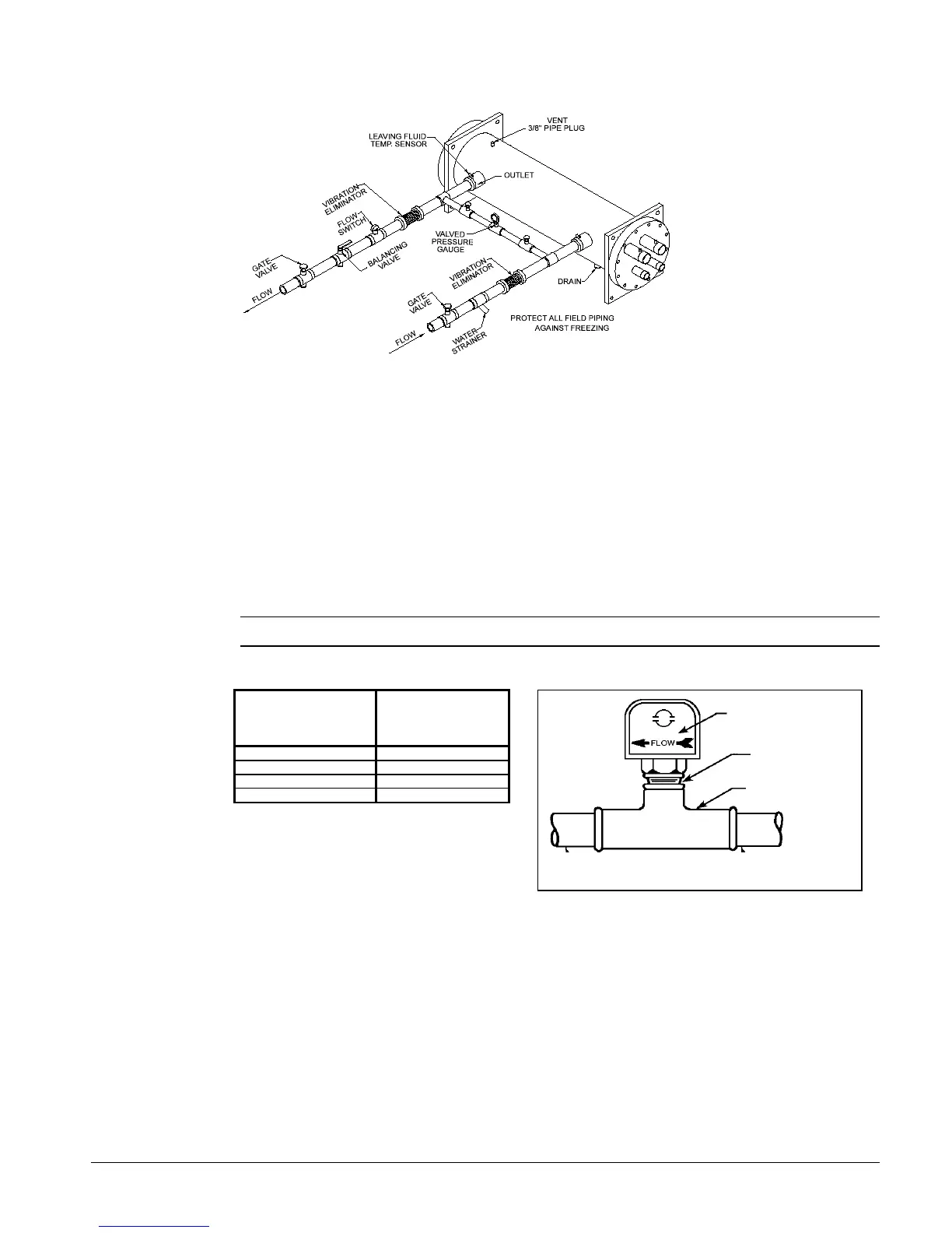
Figure 5, Typical field evaporator water piping
Flow Switch
Mount a water flow switch in either the entering or leaving (recommended) water line to shut down
the unit when water flow is interrupted.
A flow switch is available from McQuay (part number 0017503300). It is a “paddle” type switch and
adaptable to any pipe size from 3” (76mm) to 8” (203mm) nominal. Certain minimum flow rates are
required to close the switch and are listed in Table 3. Installation should be as shown in Figure 6.
Connect the normally open contacts of the flow switch in the unit control center at terminals 5 and 6.
There is also a set of normally closed contacts on the switch that can be used for an indicator light or
an alarm to indicate when a “no flow” condition exists. Freeze protect any flow switch that is
installed outdoors.
NOTE: Differential pressure switches are not recommended for outdoor installation.
Table 3, Flow Switch Minimum Flow Figure 6, Flow Switch Installation
NOMINAL PIPE SIZE
INCHES (MM)
MINIMUM REQUIRED
FLOW TO
ACTIVATE SWITCH -
GPM (L/S)
3 (76.20 30.00 (1.90)
4 (101.6) 39.70 (2.50)
5 (127.0) 58.70 (3.70)
6 (152.4) 79.20 (5.00)
Water Connections
Bring water piping to the evaporator through the side, between the vertical supports.
Refrigerant Charge
All units are designed for use with R-22 and other refrigerants. See nameplate for specific refrigerant
used. Units are shipped with an operating charge and ready for operation. The operating charge
(using R-22) for each unit is shown in the Physical Data tables beginning on page 13.
Flow direction marked
on switch
1" (25mm) NPT flow
switch connection
Tee
 Loading...