10 OM AGSD-1
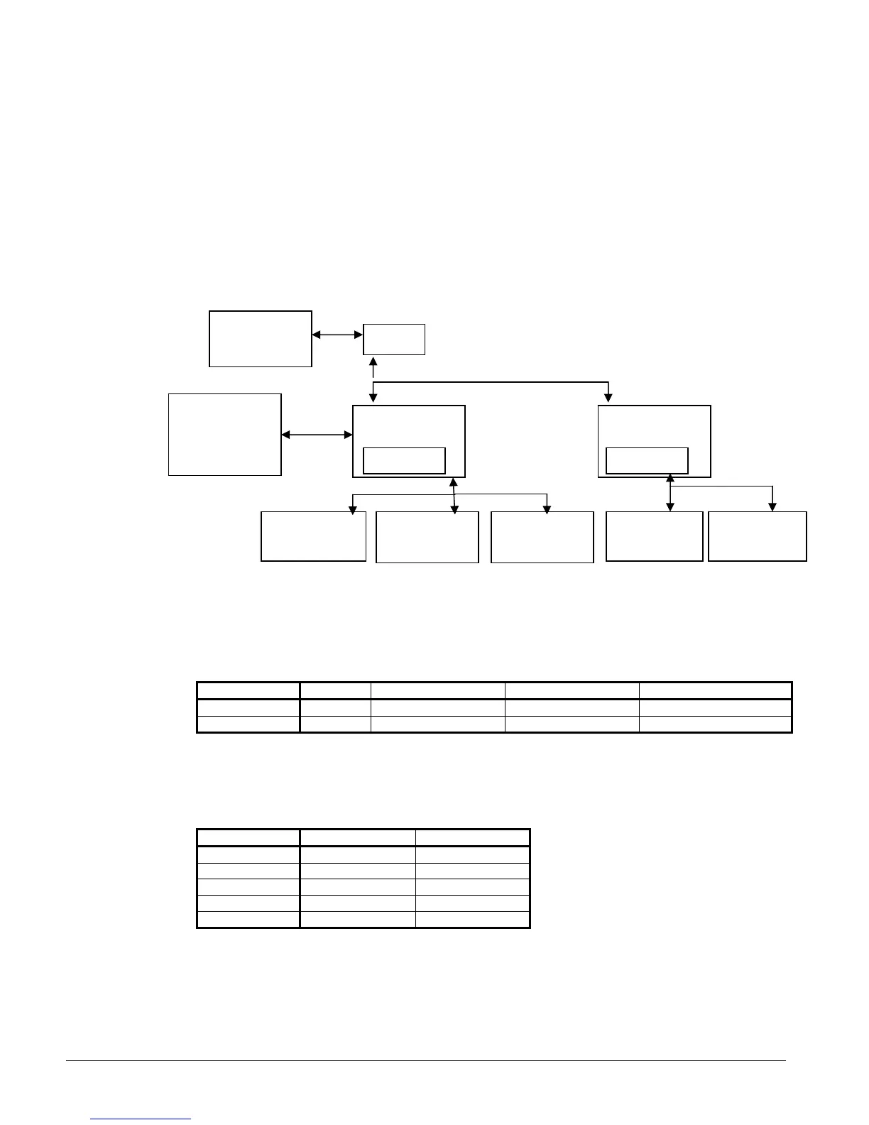
System Architecture
One large controller (CP1) is used on 2 circuit chillers (AGS 225 through 300) and a
second large controllers (CP2) is added on 3 circuit chillers (AGS 330 through 450).
Expansion I/O boards are used and communicate via a tLan (J23). Two are used on 2
circuit chillers and four are used on 3 circuit chillers. Expansion I/O board #3 is used
when additional pump or circuit status enable options are ordered.
A block diagram is shown below
Figure 3, System Block Diagram
NOTE: RAI=Remote Access Interface, EXB=Expansion Board
Table 1, pLAN Addressing
A pLAN is used to connect CP1 and CP2.
Controller Address Dip Sw 1 Position Dip Sw 2 Position Dip Sw 3 Position
Large 1 (CP1) 1 Up Down Down
Large 2 (CP2) 2 Down Up Down
Table 2, tLAN Addressing
A tLAN is used to connect the expansion modules to CP1 and CP2
Controller Expansion Serial Address
Large 1 PCOe1 1
Large 1 PCOe3 3
Large 1 PCOe4 4
Large 2 PCOe5 1
Large 2 PCOe8 4
BAS
Interface-
Bacnet,
Modbus
Large
Controller CP1
4X2
L
D
Large
Controller CP2
4X20LCD
RS485
Expansion
I/O (EXB5)
Expansion
I/O (EXB8)
RS485
Expansion
I/O (EXB4)
Expansion
I/O (EXB3)
RS485
pLAN
Expansion
I/O (EXB1)
RAI
Service
Tool(option)
 Loading...