Product Manual ALR2-3 ALR 110F – 150F 41
Line Sizing
Line sizing and layout should follow procedures found in the ASHRAE Handbooks or other
recognized design manuals. Nominal circuit capacities are listed in Table 17. Unloading steps are
found in the Physical Data tables.
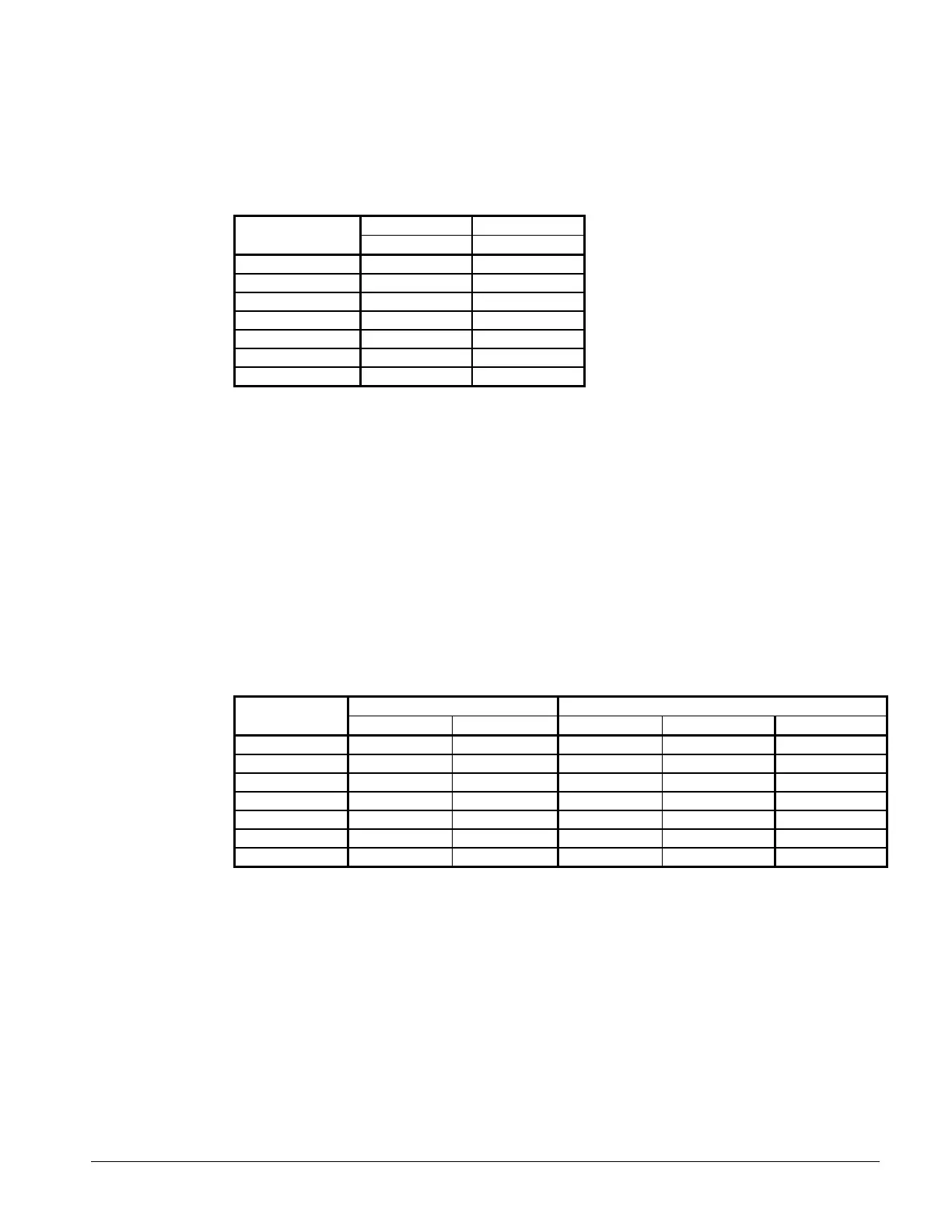
Table 17, Nominal Circuit Capacities
Circuit 1 Circuit 2
ALR Model
Tons (kW) Tons (kW)
110F 53 (185) 57 (200)
120F 60 (210) 60 (210)
130F 65 (227) 65 (227)
135F 68 (238) 68 (238)
140F 70 (245) 70 (245)
145F 73 (255) 73 (255)
150F 70 (245) 80 (280)
Dimensions
Use the ALR dimension drawing, Figure 10, for the ALR with remote evaporator. The refrigerant
connections are located approximately where the refrigerant connections to the unit mounted
evaporator are on a packaged chiller. The remote evaporator dimensions are on Figure 24.
Weights
Weights for the remote evaporators are listed on the following dimension page. Weights for the
outdoor unit can be calculated by subtracting the evaporator weight from the total unit weight found
in the Physical Data section.
Connection Sizes
Table 18, Connection Sizes
ALR Unit Remote Evaporator
Unit Size
Suction (IDS) Liquid (IDS) Suction (IDS) Liquid (IDS) Water (in.)
110 2 5/8 1 1/8 3 1/8 1 5/8 5
120 2 5/8 1 1/8 3 1/8 1 5/8 8
130 2 5/8 1 1/8 3 1/8 1 5/8 8
135 2 5/8 1 1/8 3 1/8 1 5/8 8
140 2 5/8 1 1/8 3 1/8 1 5/8 8
145 2 5/8 1 1/8 3 1/8 1 5/8 8
150 2 5/8 1 1/8 3 1/8 1 5/8 8
 Loading...