304 C – 02/06 D – pag. 8/16
After the alarms have been cleared either with automatic reset or by pressing the and buttons simultaneously for 5
seconds (for alarms with manual reset), the controller will restore normal operating conditions:
• the buzzer turns off
• the alarm relay disenergizes
• the temperature value blinks no longer
• the alarm code disappears from the LCD
If the alarm condition persists, the actions described above will be performed again.
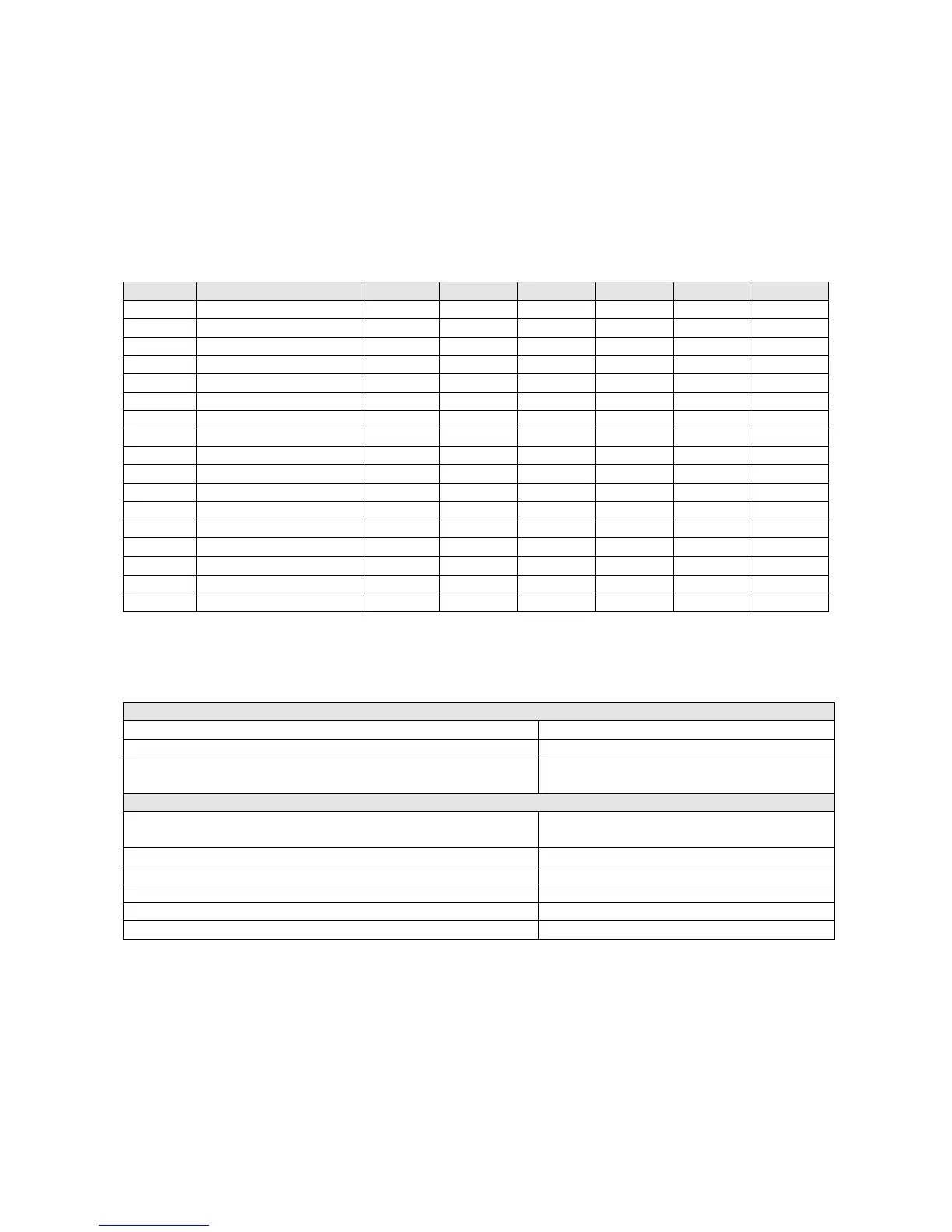
Alarm table
Display Tipo comp. pump fan resist. valve alarm
H1 high pressure OFF - ON - - ON
L1 low pressure OFF - OFF - - ON
t1 overload OFF OFF OFF - - ON
FL flow detector OFF OFF OFF - - ON
E1,E2,E3 probe OFF OFF OFF - - ON
n1 automatic timer - - - - - -
EE eeprom run - - - - - -
EL zero crossing - - - - - ON
d1 defrosting ON - - - - - -
r1 defrosting error - - - - - -
A1 antifreeze OFF OFF - - ON
LO low ambient temperature - - - - - ON
EU low supply voltage - - - - - -
EO high supply voltage OFF OFF OFF OFF OFF OFF
EP eeprom boot OFF OFF OFF OFF OFF OFF
Cn discon. remote terminal - - - - - -
Ht high temperature - - - - - ON
Electrical features
Power supply
Voltage supply range 24V -15%...+10% 50/60 Hz (20,4V~ 26,4 Vac)
Maximum power absorbed by the device 3 W
Characteristics of the fuse (obligatory) to be inserted in series
to the unit power supply
315mAT
Power driving
Below, as “Group A” is defined the grouping
of the following outputs
valve, pump, compressor, resistance
Max. current for each power connector 2 A
Relay output current (each relay, resistive load) 2A 250 V~
Relay output current (maximum 1 relay, resistive load) 3A 250 V~
Switching maximum number (each relay) 70000
Switching maximum number (each relay) 10 s
Microprocessor ALZ 022.2 ÷ 038.2
"µchiller" is based on two integrated systems (the 'Base' section including controller, inputs and outputs, and the
'terminal' section with User Interface functions). The Base and Terminal components can be enhanced by adding
optional boards allowing further auxiliary functions.
 Loading...