Page 22 / IM 778
Field Installed Options on MicroTech 2000 Units
MicroTech 2000 units can provide up to 4-outputs, that can
be configured for any of the following output control
signals:
1) Scheduled Output
When using a Network Master Panel (NMP) these out-
puts can be assigned to one of 32 available schedules.
The output will energize when the assigned schedule is
occupied and de-energize when unoccupied. These out-
puts could be used to control lights, etc.
2) Auxiliary Heat (Skin Heat)
When using a Loop Water Controller (LWC) the
MicroTech 2000 receives loop water temperature infor-
mation from the LWC and will use the Auxiliary Heat out-
put for heating when loop water temperature is inappro-
priate for heat pump heating. These outputs provide a
signal that can be used to control a remote electric
heater. The output will energize on a call for electric heat
and de-energize when not required.
3) Fresh Air Damper
These outputs provide a signal that can be used to con-
trol a remote fresh air damper. The output will energize
when the unit fan is energized and de-energize when the
unit fan is de-energized.
4) Motorized Water Valve
These outputs provide control for a motorized water
valve that can be used to stop or divert flow away from
the WSHP when compressor operation is not needed.
The output will be energized when compressor operation
is required.
If more than one of the above control signals is required on
a single WSHP, the MicroTech 2000 Auxiliary Module Kit
(107239001) must be used and these additional output con-
trol signals will be connected to the Auxiliary board. The
Auxiliary board is provided in all 2-circuit units. 1-circuit
units can provide up to 4-outputs while 2-circuit units only
have 3-outputs available. The 4th control signal output
shown in the diagrams below is not available on 2-circuit
units.
If the Auxiliary board is added in the field to provide addi-
tional outputs it will need to be mounted within the WSHP
control box so that J1 on the Auxiliary board can be con-
nected to J6 on the MicroTech 2000 board without exceed-
ing a maximum wire length of 10
"
.
Also, each output is by default configured to “none” and
must be field set to one of the four signal types listed above
using the Monitor software, cable, and a PC communicat-
ing to the unit through an MCG panel.
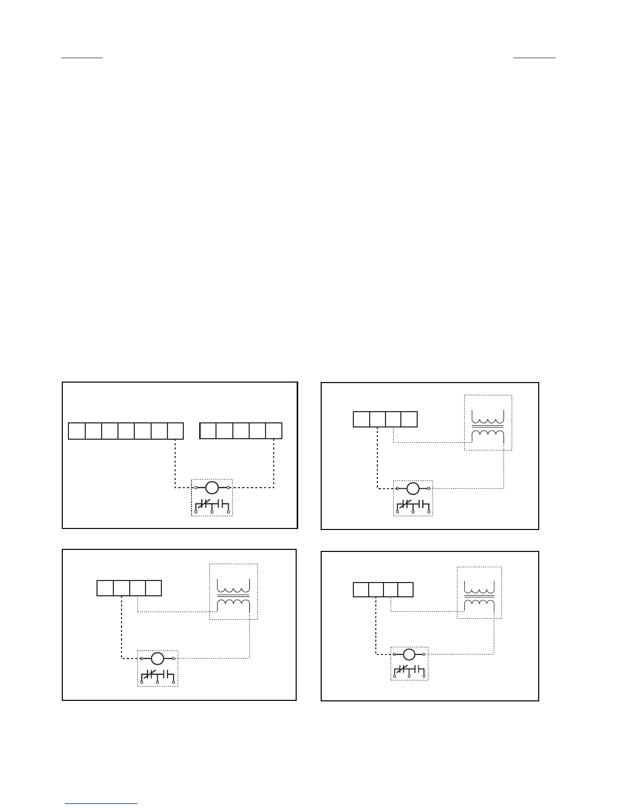
1st Control Signal Output
2nd Control Signal Output
3rd Control Signal Output
4th Control Signal Output
Terminal Boards
(Located externally on the WSHP chassis)
24VAC
Pilot Duty Relay
(by others)
Terminals Located on
Microtech 2000 Auxiliary Board
J6
24VAC
Pilot Duty Relay
(by others)
Use contacts as needed for option
Terminals Located on
Microtech 2000 Auxiliary Board
J7
24VAC
Pilot Duty Relay
(by others)
Use contacts as needed for option
Terminals Located on
Microtech 2000 Auxiliary Board
J10
24VAC
Pilot Duty Relay
(by others)
Use contacts as needed for option
IMPORTANT:
To use onboard 24VAC, change
the jumper PF1 on the
MicroTech 2000 controller from
factory default pins 1 and 2 to
pins 2 and 3.
 Loading...