4. INSTALLATION
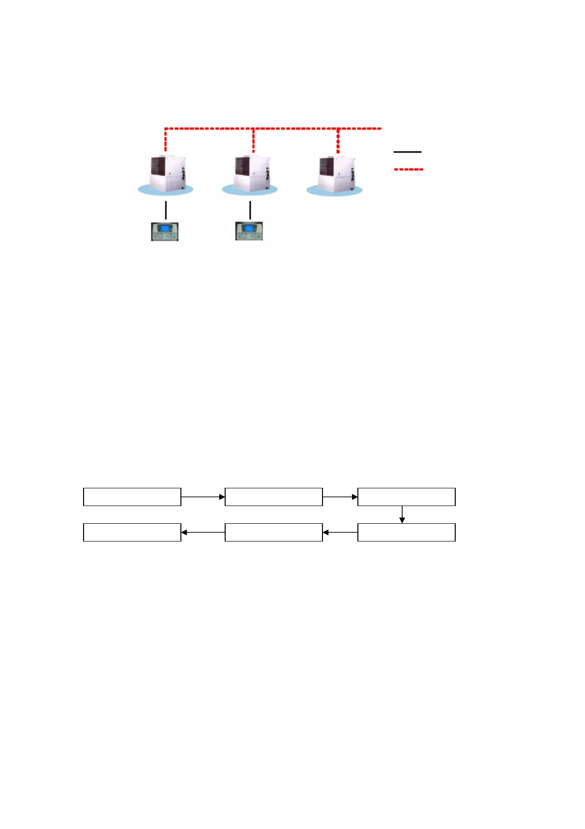
4.1 Chiller Bus
Su
orted u
to 50 units of Chille
Chiller 0 Chiller 1 Chiller 2
5 way wire (CN8)
Chille
Communication bus
Chille
Panel 1
(Slave)
Chiller Panel 0
(Master)
CHILLER NETWORK
Chiller panel needs to be energized with +12Vdc. The 5 way wires that provided is once on the easiest solution to
establish a communication between the panel and chiller main board (CN8-CN8). If the 5-way wires socket has been
occupied in main board, just using 2 insulation wires connected to the +12Vdc and GND terminal block from main
board to panel can still energize a panel. Beside that, another 2 insulation wired are needed to establish a
communication between panel and chiller main board.
Chiller panel can support maximum up to 50 units of chiller. In the chiller network, duplication of main board unit
address is not allowed. Each chiller main board should have their unique unit address (0 – 50).
For first time running, user need to assign a unique unit address to each main board in the chiller network. User
should follow the procedure below:
x Only power ON one main board at once time. Make sure not others main boards are energized.
x By using the panel connected to the main board.
<ENTER> <ENTER>
Summary Pages Main Menu Settings Menu
1. General Set ParameterG7 Unit No
<ENTER>
<ENTER>
Key in “0001” as
password
<ENTER>
x
Key in a unique unit address and press ENTER to execute.
x De-energized the main board and repeat the procedures again until all the main boards have been assigned a unique unit
address
IMPORTANT: Do not assign a same unit address to more than one chiller main board.
RECOMMENDATION: Please select a coherent model (G1 Model) to all the chiller main boards in the same
network
6
 Loading...