McQuay IM 987 89
Unit Options
control panel). The RH Lvl Pos= parameter indicates the
current position of the vane for the right-hand
DesignFlow station (control panel side).
Important: Wait several seconds until the value on the
keypad stabilizes before taking the reading.
For detailed information regarding operation and
navigation through the unit keypad, refer to Operation
manual OM 137 (discharge air control units) or OM 138
(zone control units).
6 Confirm the value of the reading. Ideally, it should read
close to 20.00 (19.50 to 20.50 is acceptable). If the
reading is out of range, loosen the screws fixing the
mechanical stop at the top of the assembly, make a small
adjustment, and recheck until the reading is in the
specified range.
Note: Generally, adjustments should not be necessary.
7
Locate the leveling component kit, which is shipped with
the unit, in the unit mail control panel.
8 Duct tape the fulcrum alignment plate to the bottom
corner of the vane (see Figure 99) aligning it as follows:
a The bottom edge of its notches should be flush with
the bottom edge of the vane.
b The side of one notch should be even with the bend
near the outer edge of the vane.
c The plate should be flat against the outer surface of
the vane.
Figure 99: Tape Fulcrum Alignment Plate to Vane
9 Locate and install the fulcrum used in the leveling
procedure as follows (see Figure 99):
a Wipe the bottom of the louver door where the fulcrum
will be located so that the duct tape will stick to it.
b Pre-apply duct tape to the top surface of the bottom
portion of the fulcrum, extending it about one inch
beyond the edges on three sides.
c With the alignment plate taped to the vane and the
vane in the zero airflow position, locate the fulcrum
parallel to and against the alignment plate.
Note: The zero airflow position is when the vane is swung
away from the back wall and gently resting against
its stop.
d
Once the fulcrum is in position, press the duct tape
extensions down to hold the fulcrum in place.
e Remove the alignment plate after installing the
fulcrum.
10 Close and latch the louvered intake door.
11 Remove the cover from the access opening in the bottom
blade of the outdoor air intake louver (see Figure 102,
page 90).
12 Verify that the unit fans are off and that the outdoor air
dampers are closed. If there is a wind, cover the outdoor
air louvers with poly film, cardboard, or other suitable
material to prevent adverse readings due to wind.
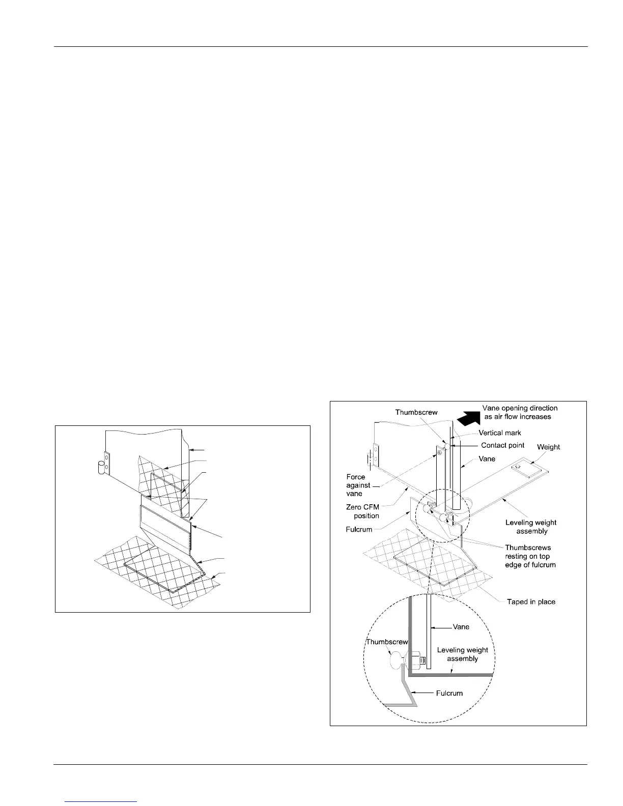
13 Rest the leveling weight assembly on the fulcrum, as
shown in Figure 100, so that:
a Its bottom two thumbscrews rest on the top edge of
the fulcrum.
b Its top thumbscrew rests against the vertical
alignment mark on the vane.
Note: The alignment mark is located 0.50 inch in from the
bend on the outer edge of the vane. It intersects with
a hole located one inch up from the bottom outer
edge of the vane.
Figure 100: Place Leveling Weight On Fulcrum
D u c t T a p e
V a n e
F u l c r u m
A l i g n m e n t
P l a t e
T h i s E d g e
F l u s h w i t h
B o t t o m o f V a n e
T h e s e E d g e s
F l u s h w i t h
B o t t o m o f
V a n e
D u c t T a p e

 Loading...


